
Examines the application of the gas laws to Air Compressors and Motors.

View versions (4)

Introduction

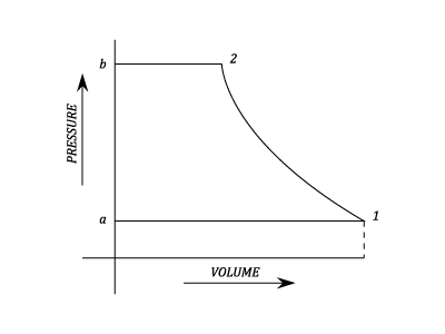
Single Stage Reciprocating without Clearance:
23287/Air-Compressors-0020.png

Stage 1 - a

  • Suction Stroke: The inlet valve opens and the cylinder fills with air at Ambient Pressure.
\text{Work done}=P\;dV=P_1V_1
(1)

Stage 1 - b

  • Compression Stroke: Both Valves are shut. The Pressure is raised from P_1 to P_2.

Stage 2 - b

  • Delivery Stage: The Exhaust Valve opens. Air at P_2 is delivered to the receiver at Constant Pressure.
\text{Work done}=P_2V_2
(2)

The Work Done during compression = \displaystyle\frac{P_2V_2-P_1V_1}{n-1}

The Work Done in the Compressor = \displaystyle \frac{n}{n-1}\;(P_2V_2-P_1V_1)

=\frac{n}{n-1}\left(P_2V_2 - P_1V_1 \right)
(3)
\therefore\;\;\;\;\;\;\;\text{Net Work Done}=P_1V_1-P_2V_2+\frac{P_2V_2-P_1V_1}{n-1}
(4)

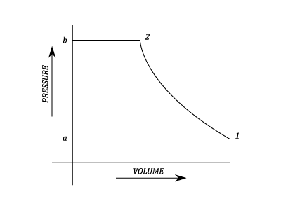
Work done in an Isothermal Compression
23287/Air-Compressors-0021.png

Work Done on Air

=P_2V_2+P_1V_1\;Ln \frac{V_1}{V_2}-P_1V_1
(5)

But,

P_1V_1=P_2V_2
(6)
\therefore\;\;\;\;\;\text{Work Done}=P_1V_1\;Ln\frac{V_1}{V_2}
(7)

or,

P_1V_1\;Ln\frac{P_2}{P_1}
(8)

Work Done in an Adiabatic Compression

\text{Work Done}=\frac{\gamma }{\gamma -1}\left(P_2V_2-P_1V_1  \right)
(9)
=\frac{\gamma }{\gamma -1}\;wR\;\left(T_2-T_1  \right)
(10)
=w\;C_P\left(T_2-T_1 \right)=\text{The Increase in Enthalpy}
(11)

Alternative Forms of the Work Done Expression

The Work Done is given by the following Expressions:

\frac{n}{n-1}\left(P_2V_2-P_1V_1 \right)
(12)
\frac{n}{n-1}\;wR\left(T_2-T_1 \right)N
(13)

where N is the number of Cycles per Min.

\frac{n}{n-1}\;WR\left(T_2-T_1 \right)
(14)

where W is the weight Handled per Min.

\frac{n}{n-1}\;wRT_1\left(\frac{T_2}{T_1}-1\right)
(15)

or,

\frac{n}{n-1}\;wRT_1\left[\left(\frac{P_2}{P_1} \right)^{\frac{n-1}{n}}-1 \right]
(16)

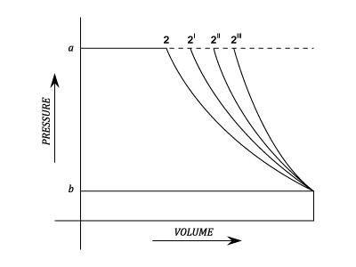
A Comparison of the Work Done with different Indices of Compression
23287/Air-Compressors-0022.png
P_1V_1^n=P_2V_2^n
(17)
V_2=V_1\left(\frac{P_1}{P_2} \right)^{\frac{1}{n}}
(18)
\therefore\;\;\;\;\;V_2=\frac{V_1}{R^\frac{1}{n}}
(19)

where R =Pressure Ratio.

Points on the Graph:-

  • 2 Isothermal. n = 1
  • 2' Compression when \gamma \geq n\geq 1
  • 2'' n = \gamma - Adiabatic Reversible.
  • 2''' n\geq \gamma

For Reciprocating Compressors:

The efficiency referred to is the Isothermal case since fairly successful cooling can be achieved.

\text{Isothermal}\;\eta =\frac{\text{Work Input with Isothermal Compression}}{\text{Work Input required with actual index n}}
(20)

For Rotary Compressors:

The Cooling is very difficult and Indices of less than \gamma are never achieved. It is therefore normal to compare the Performance with the Adiabatic reversible case.

\text{Adiabatic} \eta =\frac{\text{Work Input with Adiabatic Reversible Compression}}{\text{Work Input required with actual index n}}
(21)

The Overall Isothermal Efficiency of the Plant:

\text{Transmission Efficiency} \eta_T=\frac{\text{Work In put at Compressor Drive}}{\text{BHP of Motor Supplying Power}}
(22)
\text{Mechanical} \;\eta_M \;\text{of Compression} = \frac{\text{Work Done on Air in Cylinder}}{\text{Work In put at Compressor Drive}}
(23)
\text{Overall Mechanical}\;\eta =\eta _T - \eta _m
(24)
\text{Overall isothermal}\;\eta =\frac{\text{Work Done on Air in Cylinder with isothermal Compression}}{\text{BHP of Motor}}
(25)
\;=\text{Overall mechanical}\;\eta \times \text{The Isothermal} \;\eta\;\text{of compression}
(26)

The Cooling of Compressors.

It is usually considered that the heat is given up during the Compression:

For a Polytropic Compression.

\text{Heat Rejected} =\left(\frac{\gamma -n}{\gamma -1} \right)\times \left(\text{Work done on Air during the compression stroke}\right)
(27)

For an Isothermal Compression.

\text{Heat Rejected} = \text{Work done on Air}= P_1V_1\;ln\;\frac{P_2}{P_1}
(28)
Example 1 [imperial]
Problem

An Air Compressor takes in Air at 14 psi and at 20 degrees C. It is compressed in accord to the law P\;V^{1.2}=Constant and delivers it to receiver at 140psi.

Find the Temperature at the end of the Compression and Calculate per pound of Air, the Compressor Work input and the heat rejected during Compression.
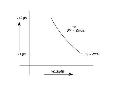
Workings
23287/Air-Compressors-0023.png
P\;V^{1.2}=\text{Constant}
(29)
\frac{P_1}{T_1^{\frac{1.2}{0.2}}}=\frac{P_2}{T_2^{\frac{1.2}{0.2}}}
(30)
\therefore\;\;\;\;\;T_2=T_1\left(\frac{P_2}{P_1} \right)^{\frac{0.2}{1.2}}=293\left(\frac{140}{14} \right)^{\frac{0.2}{1.2}
(31)

=429^{\circ}K

Work input to Compressor per lb.

=w\;R\times \left(\frac{n}{n-1 \right)\times \left(T_2-T_1 \right) }
(32)

=96\times \frac{1.2}{0.2}\left(429-293 \right)=78,300\,ft.lb.

Heat Rejected during Compression.

\text{Heat Rejected}=\frac{\gamma -n}{\gamma -1}\times \text{Work Done in Compression}
(33)
=\frac{\gamma -n}{\gamma -1}\times \frac{wR(T_2-T_1)}{n-1}
(34)
=\frac{\gamma -n}{\gamma -1}\times \frac{78,300}{1.2}=\frac{1.4-1.2}{0.4}\times \frac{78,300}{1.2}\times \frac{1}{1400}
(35)

= 23.4\;CHU

Solution

Temperature at the end of the Compression 429^{\circ}K

Compressor Work input 78,300\,ft.lb.

Heat Rejected during Compression 23.4\;CHU