
Struts
An analysis of Struts using the EULER Formula.
By definition any member of a structure which is in Compression may be called a Strut. However, the term is usually reserved for long slender members which are likely to fail through buckling, rather than from compressive stress.
As a structural member resisting longitudinal compression, a strut is commonly used in architecture and engineering. In relation to engineering applications, such as for automobiles and aeronautical structures, a strut can be used as a passive brace to reinforce the body, or as an active stress bearing component. As an example, lift struts (still used today on small light aeroplanes) are commonly employed to carry both tension and compression as the aircraft maneuvers in flight.

Description
The resistance of any member to bending is determined by it's flexural rigidity EI, but
where, A is the cross sectional Area and k is the radius of gyration.
So for a given material, the Load per unit area which a member can withstand is related to k. There will be two principal moments of Inertia and off these the least is taken.
The Slenderness Ratio is given by :
i.e
The value of this ratio will determine whether a member falls into the category of Struts or Columns. Struts which fail by buckling before the limiting compressive stress is reached , can be analysed by the Euler Theory.
Pin ended Strut axially loaded.
It is assumed that the Strut is initially straight and that the compressive load is applied axially.
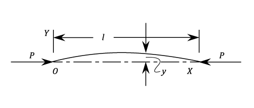
Applying the equation of bending of beams:
Substituting
The Solution of which is given by:
when x = 0 and y = o then B = 0 when x = l and y = o then
From which either A = 0 and as a result y = 0 for all values of x. In this case the strut will not buckle. Or A is indeterminate. The least value to satisfy is
.
This corresponds to
From this it is possible to obtain the least value of P which will cause the Strut to buckle. This is called the Euler Crippling Load where,
It must be stressed that the value of "I" used here is the least Moment of Inertia.
The interpretation of this analysis is that for all values of P other than those which make , the Strut will remain perfectly straight
. For the particular value
and
, the strut is in neutral equilibrium and theoretically any deflection which it is given, will be maintained. This is subject to the limitation that "l" remains reasonably constant and in practice any slight increase in load at the critical value will cause the deflection to increase appreciably until the material fails by yielding. Neither the Maximum stress nor the Deflection are proportional to the load.
Example 1 [imperial]
A straight Alloy bar 35 inches long and with a cross section of 1/2 and 3/16 inches, is mounted in a strut testing machine. It is loaded until it buckles. Assuming that the Euler Formula applies, estimate the maximum central deflection before the material attains it's yield point of 18 Tons/in\^2. E = 4690 Tons/in\^2.
There will be no deflection until the Euler load is reached. This load is given by:
The Maximum Bending Moment occurs at the centre where:
The Maximum Stress is the sum of Direct and Bending stress at the centre.
The maximum deflection = 5.05
Example 2
A uniform bar of cross sectional area A and flexural stiffness EI is heated so that it's temperature varies linearly from 1/2t at one end to t at the other. One is pin jointed to a rigid foundation and the other is pin jointed so that tit can slide in the direction of the length of the bar. The thermal expansion is resisted by a compression spring of stiffness k. If there is no load in the spring when t = 0, obtain an expression for the stress in the bar when it is heated and show that it buckles in flexure when:
where is the linear coefficient of thermal expansion
The average temperature along the bar is and hence the thermal expansion is
If P is the force exerted by the spring on the bar, the compression produced is and the compression of the spring is
Net expansion of bar = compression of spring
Thus
The bar will buckle when and substitution in the above gives:
Rearranging
Direction fixed at Both Ends
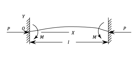
Assume that the Strut has deflected and that there is a bending moment at the ends.
Then,
Putting
Then,
When x = 0 ; y = 0
And since
When x = l ; y = 0
Note. This case is equivalent to a pin-ended Strut of length . To allow for imperfect fixing it is common to allow an equivalent length of between 0.6 an 0.8 times the length l.
Partial Fixing of the Ends
Example 1 [imperial]
A Strut of length 2a has each end fixed in an elastic material which exerts a restraining Moment per unit of angular displacement. Prove that the critical Load P is given by the equation
where
. Such a Strut 8ft. 4in. long has a critical load of 3,500 lbs. on the assumption that it is pin ended. Determine the percentage increase in the Critical Load is the constraints offered at the ends is 1,55 lb. in per degree of Rotation.
If M be the restraining Moment at both ends then
Using the notation given in the question.
At ,
and
And
Thus
At the centre ,
i.e.
For pinned ends:
Substituting in equation (37)
The least solution of this equation is . This is an increase of 78% over the value for pin ended
This is an increase of 78% over the value for pin ended
Direction fixed at one end and free at the other
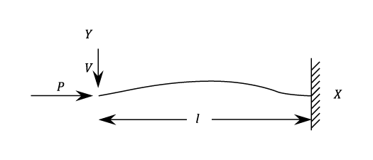
This is clearly the same as a pin ended strut of length 2l
hence
Direction fixed at one end and Position fixed at the other
Let V be the lateral force required to maintain the position of the pinnend end.
If
From which,
When x = 0 , y = 0
When x = l , y = 0
And when
From which,
or
Strut with an Eccentric Load
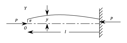
If e is the eccentricity of the Applied Load, and the deflection y is measured from the line of action of the load ( see diagram).
Then
Then as before:-
When x = 0, y = e and therefore B = e When and
Thus,
Note: for an eccentric load the strut will deflect for all values of P and not only for the critical Value. The deflection will become infinite for giving the same crippling load
. However, due to the additional bending moment set up by the deflection, the Strut will always fail by compressive stress before the Euler Load is reached.
The Maximum Bending Moment is given by:-
The Maximum stress
is obtained by combing the bending and direct stress.
Strut with Initial Curvature
These are treated as a beam with an initial radius of curvature such that:-
Using Equation 10 "Bending of Curved Beams"
Thus
Under an end load P, the initial shape of the strut may be assumed to be circular, parabolic or sinusoidal without making much difference to the final result. But the most convenient form is:
This satisfies the end conditions and corresponds to a maximum deviation of c . Any other shape could be analysed into a Fourier series of sine terms.
Then,
The complete solution of which is :
When and
then
and when and
then
Hence,
The Crippling load is
And
Example 1
A Strut of length l is encased at it's lower end. The upper end is elastically supported against lateral deflection so that the resisting force is k times the end deflection. Show that the crippling load is given by:
where
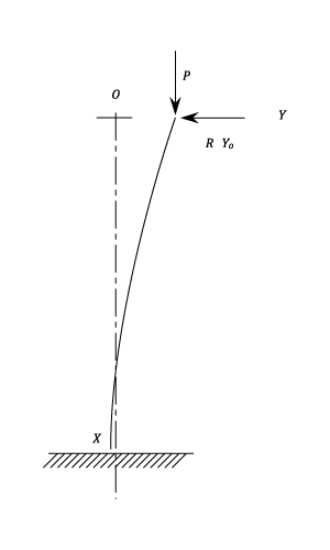
Taking Axes as shown. If is the end deflection
From Which:
When x = 0 y =
When x = l, y = 0
And
Substituting this value for A in equation (4)
Example 2
A Tubular steel Strut is 2.5 in. external diameter and 2 in. internal diameter. It is 8 ft. long and has hinged ends. The load is parallel to the axis but eccentric. Find the maximum eccentricity for a crippling load of 0.75 times the Euler Value. The yield stress is 45,000 lb./sq.in and
The Euler load is given by:
The actual load to cause failure
For an eccentricity e:
Maximum Stress 45,000
The maximum eccentricity = 0.205 in