
Shear Stress in Beams
A shear stress is defined as the component of stress coplanar with a material cross section. Shear stress arises from a force vector perpendicular to the surface normal vector of the cross section.
-\b{beams}, also known as
-\b{beams}, are beams with an
- or
-shaped cross-section. The horizontal elements of the
are flanges, while the vertical element is the web. The web resists shear forces while the flanges resist most of the bending moment experienced by the beam.
An analysis of Shear Stress in Beams of various cross sections.
Introduction.
This page should be read in conjunction to " Engineering Materials, Shear Stress"
Variation of Shear Stress.
The Shearing Force at any cross section of a Beam will set up a Shear Strain on transverse sections which in general will vary across the section.
In the following analysis it has been assumed that the Stress is uniform across the width (i.e. parallel to the neutral axis), and that the presence of shear stress does not affect the distribution of Bending Stress.
This last point is not strictly true because the presence of Shear Stress will distort the transverse planes which will no longer remain plane (See "Bending of Beams Part 4). Due to the Shear Stress on transverse planes there will be complementary planes parallel to the neutral axis.
In the following diagram two transverse sections are shown at a distance apart, and the Shearing forces will be
and
whilst the Bending Moments are
and
.
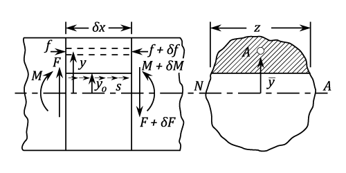
Let,
- s be the value of the complementary shear stress and hence the transverse shear stress at a distance
from the Neutral Axis.
- z be the width of the cross section at
- A be the area of cross section cut off by a line parallel to the Neutral Axis.
be the distance of the centroid of A from the Neutral Axis.
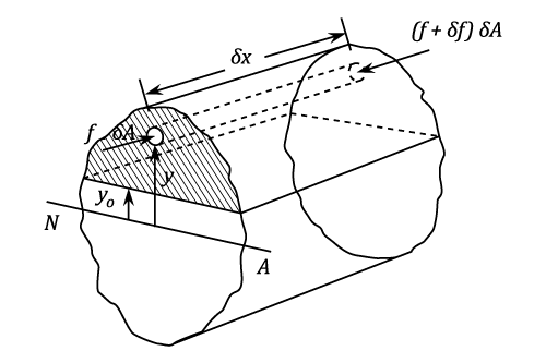
and
are the Normal Stresses on an element of Area
. There is a difference in Longitudinal Forces equal to
and this summed over the area A must be in equilibrium with the transverse Shear Stress s on the longitudinal plane of area
Thus,
But
And
Substituting in equation (#1) or,
Note: . See "Shearing Force and Bending Moments.
It should also be noted that is the actual width of the section at the position where
is being calculated, and that
is the Total Moment of Inertia about the neutral axis. In some applications it is advantageous to calculate
as several parts.
Rectangular Sections.
For a rectangular section at any distance from the Neutral Axis :
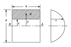
Substituting in equation (#2) and putting
This shows that there is a parabolic variation of Shear Stress with . The maximum Shear Force occurs at the Neutral Axis and is given by:
If
is called the Mean Stress, then:
I-Section
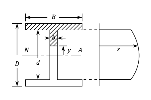
The dimensions are shown in the diagram. It is required to find an expression for the Shear Stress in the Web.
is made up of two parts as follows:-
- for the flanged area
- for the web part
Using Equation (#2) and noting that ,
As with the rectangular section, the maximum transverse Shear Stress is at the neutral axis.
At the top of the web,
Since the Shear Stress has to follow the direction of the boundary, the distribution must be of the form shown becoming horizontal at the flanges.
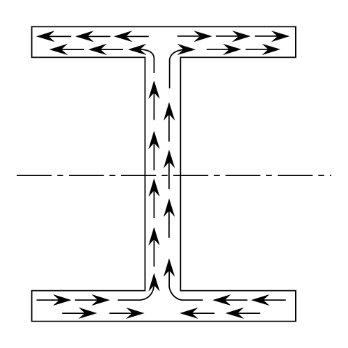
Consequently, the complementary Shear Stress in the flanges is on longitudinal planes perpendicular to the neutral axis and the "width z" is replaced by the flange thickness
Then,
Showing that the Shear Stress in the flanges varies from a maximum at the top web to zero at the outer tips.
In Practice, however, it will be found that most of the Shearing Force (about 95%) is carried by the Web and the Shear Force in the flanges is negligible.
As the variation over the web is comparatively small (about 25%) it is convenient for design purposes and also in calculating deflection due to Shear; to assume that all the Shearing Force is carried by the Web and is uniformly distributed. Similarly, it is normal practice to assume that as a first approximation, the Bending Moment is carried wholly by the flanges.
Example 1 [imperial]
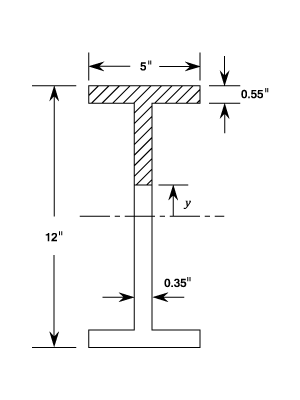
A 12 in. by 5 in. British Standard Beam is subjected to a Shearing Force of 10 tons.
Calculate the value of the transverse Shear Stress at the Neutral Axis and at the top of the Web and compare this with the mean Stress calculated on the assumption that the Stress is uniformly distributed over the Web.
What percentage of the Shearing Force is carried by the Web?
Area=
Web Thickness=
and Flange thickness=
At the Neutral Axis
At the Top of the Web ()
Assuming that all the Shearing Force is carried uniformly by the web.
The Total Shearing Force carried by the web is given by:
i.e.
of the Total
The remaining 5 % of the vertical Shear Stress is presumably accounted for by the component of the Shear Stress at the junction of the flange and the web.
Failure due to Shear in the Web usually takes the form of buckling brought about by the Compressive Stresses on planes at 45 degrees to the transverse section. ( See Compound Stress and Strain). For this reason deep webs are often supported by vertical stiffeners.
- Percentage of the Shearing Force is
of the Total.
Principle Stresses in I-Beams.
When an section beam is subjected to both Bending and Shear Stresses it is normal to find that the Maximum Principle Stress is at the top of the Web. The other possible value is the Maximum Bending Stress which occurs at the outer edge of the Flange.
Example 1 [imperial]
A short vertical column is firmly fixed at the base and is 1 ft high. The column is of section 8 in. by 4 in. The flanges are 0.4 in thick and the web is 0.28 in. thick.
and
An inclined load of 8 tons acts on the top of the column in the centre of the section and in the plane which contains the centre-line of the web. The line of action is to the vertical.
Determine the position and magnitude of the greatest principle stress on the base of the column.
The inclined load will intersect the base cross-section at a distance from the centroid.
Resolving the load into horizontal and vertical components:
- Direct Load =
- Shearing Force =
- Bending Moment =
At the top of the Web:
Bending Stress =
Direct Stress =
Therefore, Total Normal Stress =
See the Reference Pages on Compound Stress and Strain (currently in preparation)
The Maximum Principle Stress =
(in Compression)
This will occur at the top of the Web.
Checking the value of the maximum Bending Stress which is:-
Which together with the direct Stress gives a maximum value of at the outside of the flange and which is less than the value at the top of the Web.
Pitch of Rivets in Built up Girders.
The load carried by one rivet in a beam section built up as shown in the diagram, is determined by the difference between normal stresses on certain areas of two transverse sections at a distance apart, equal to the pitch of the rivets.
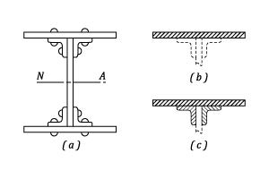
They are to be used in that part of the cross-section which " comes away" when the particular set of rivets are removed, i.e. in the case of the rivets holding the flange to the angle section the area shaded in (b), and for the rivets holding the angles to the web, the area shown in (c)
If is the pitch of the rivets and
is the force on the rivets over a length
of beam, then proceeding as in the section on the variation of Shear Stress:
(Compare with
and let
)
Note that for the flanges there are two rivets to a pitch length and they are usually staggered so as not to occur together in one cross section. Also note that the web rivets are in double shear.
Solid Circular Sections.
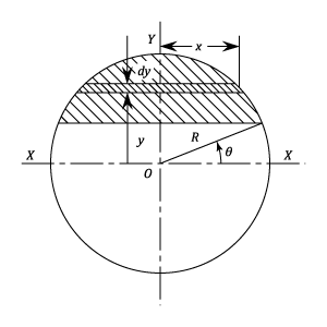
Let be the Shear Force across a chord parallel to
defined by the angle
At the Neutral Axis the Shear Stress is maximum and equals
mean shear stress
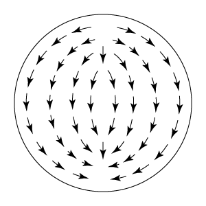
The directional distribution of the Shear Stress is as indicated. This does not affect the magnitude of the greatest Shear Stress which is usually the value required.
This particular case is applicable to Rivets in Shear, but the ratio may be assumed to have been incorporated in the allowable stress value which is then taken as uniform over the section.
Thin Circular Tubes.
It was shown in the page on Shear Stress that it has to follow the direction of the boundary. In a thin walled circular tube this means it can be assumed to be tangential.
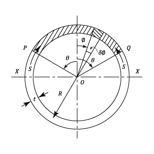
Assume that XX is the neutral axis and that P and Q are two symmetrically placed positions defined by the angle . Let the Shear Stress be s.
The complementary Shear Stress is along the longitudinal planes and is balanced by the difference of Normal Stress on the shaded area subtending the angle .
For a length of Beam ,
but,
where
Polar
where A represents the area and R the mean radius.
(See Engineering Materials , Bending Stress, Moments of Inertia)
The Maximum Shear Force will occur at the neutral axis and is given by:
Miscellaneous Sections
The Shear Stress at any point in a cross-section can always be calculated from the basic formula
Shear Centre.
For unsymmetrical sections and in particular angle and channel sections, the summation of the Shear Stresses in each leg gives a set of Forces which must be in equilibrium with the applied Shearing Force.
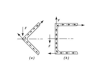
Consider the angle section which is bending about a principle axis and with a Shearing Force at right angle to this axis. The sum of the Shear Stresses produces a force in the direction of each leg as shown above.
It is clear that their resultant passes through the corner of the angle and unless is applied through this point, there will be a twisting of the angle as well as Bending. This point is known as the Shear Centre or Centre of Twist.
For a channel section with loading parallel to the Web the total Shearing Force carried by the web must equal , and that in the flanges produces two equal and opposite horizontal forces. It can be seen that for equilibrium the applied load causing
must lie in a plane outside the channel as indicated. Its position is calculated as in the following example.
Example 1 [imperial]
Explain why a single section channel with its web vertical, subjected to vertical loading as a beam will be in torsion unless the load is applied through a point outside the section known as the Shear Centre.
Find its approximate position for a channel section by
outside by
If is the Shearing Force at the section, then the Total Vertical Force in the Web can be taken to be equal to
. It should be mentioned that integrating from the height of the web only will give a value slightly less than
( Compare with Example 2) but the remaining vertical force is assumed to be carried by the corners of the section.
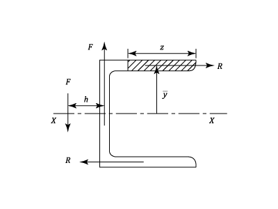
Proceeding as in the section on beams, the Shear Stress in the flanges at a distance
from the tip is:
The Total force in each Flange is given by:
If is the distance of the Shear Centre ( Through which the applied load must act if there is to be no twisting of the section) from the centre line of the Web, then for equilibrium.
Or