
Magnetic Reluctance
Key facts
The magnetic reluctance is defined as:
where is the magnetomotive force, and
the magnetic flux.
For a magnetic circuit of length , cross-sectional area
, and relative magnetic permeability
, the magnetic reluctance can be calculated with:
where is the magnetic permeability of free space.
<br/>
Constants
A description of the magnetic reluctance, also discussing a way to calculate it
The magnetic reluctance of a magnetic circuit can be regarded as the formal analog of the resistance in an electrical circuit. The magnetic reluctance can be expressed as:
where is the magnetomotive force (mmf), and
is the magnetic flux.
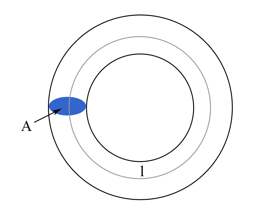
In order to calculate the magnetic reluctance, consider a magnetic circuit of length and cross-sectional area
, as diagramed in Figure 1.
We know that the magnetic field strength can be written as:
where is the current in the coil, and
is the number of turns (for a more detailed discussion on the magnetic field strength see Field Strength ). Furthermore,
can be related to the magnetic flux density
with the equation:
where is the magnetic permeability of free space, and
the relative magnetic permeability of the material.
As the magnetic flux is defined as:
equation (#3) can also be written as:
from which the magnetic field strength becomes:
Considering that is uniform, equation (#2) becomes:
Using the expression form of from (#7) in (#6), we get that:
which leads to:
As the magnetomotive force of a coil is given by:
equation (#9) becomes:
or:
\calc{l/(4*π*10^(-7)*mu_r*A)} "Instant calculator eq(13)"
Taking into account the definition of the magnetic reluctance from (#1), we get that can be calculated as:
Example 1 [metric]
Consider a toroid with the mean length of , the cross section of
, and the relative magnetic permeability of
. What is the magnetic flux and the magnetic flux density if the coil has 10 turns and the current is 2 amperes ?
As the magnetic reluctance is given by:
and, in our case, (
), and
(
), we get that:
from which we obtain:
The magnetic flux can be written as:
where , the magnetomotive force, is given by:
As, in our case, ,
, and also considering (#3), we obtain the magnetic flux:
Taking into account that the cross-sectional area is (
), the magnetic flux density becomes:
As a side note, if the toroid has an air gap of length , then its total magnetic reluctance,
, would be the magnetic reluctance of the toroid plus the magnetic reluctance of the air gap:
Thus, in this case, the total magnetic flux, , would be given by: