Under the action of radial Pressures at the surfaces, the three Principal Stresses will be (Compressive) radially , (Normally Tensile) Circumferentially and (Normally tensile) longitudinally.
These Stresses may be expected to vary over any cross-section and equations will be found which give their variation with the radius .
A cylinder is the central working part of a reciprocating engine or pump, the space in which a piston travels.
It is assumed that the longitudinal Strain is constant. This implies that the cross-section remains plain after straining and that this will be true for sections remote from any end fixing.
Let be the radial shift at a radius , i.e. after Straining the radius becomes , and it should be noted that is small compared to .
The increase in Hoop Strain (Circumferential) is given by:-
Hoop Strain = Increase in Circumference / Original Circumference
Thus the Radial Shift at an unrestrained radius of will be
. The Radial Strain = Increase in / = in the limit.
The derivation of the Strain Equations appears in " Engineering Materials/Compound Stress and Strain". Using the equations given:-
It follows from equations (1) and (7) that since is constant is constant( i.e. it is independent of ). The above analysis could have been considerably shortened if this had been assumed initially. This would have meant that equation (1) would have been reduced to : = Constant
This result coupled with the equilibrium equation (6) allows all the other equations to be obtained.
The majority of numerical problems can be solved by the application of equations (8) and (9). However, some examples may require the use of a general formula for and in terms of the dimensions and the external pressures.
Given an internal pressure of (Internal diameter , external pressure , and diameter ), it then follows that the radial stresses at these surfaces must be equal to the applied pressures and equation (8)can be written as:
Subtracting and re-arranging:
Similarly,
Thus from equation (9)
The maximum Shear Stress (i.e. half the stress difference):
It will be found that the maximum Principal Stress and maximum Shear Stress occur at the inside surface.
Internal Pressure Only
Pressure Vessels are found in all sorts of engineering applications. If it assumed that the Internal Pressure is at a diameter of , and that the external pressure is zero (Atmospheric) at a diameter , then using equation (8)
Pressure is the force per unit area applied in a direction perpendicular to the surface of an object.
And,
Solving these equations for and
The Stresses at any Diameter are:
Radial,
And
Hoop,
The Stress variations with diameter are shown in the diagram. The two curves are in effect "parallel" since (See equation (7)):
It can be seen that the maximum Hoop Stress occurs when
Thus,
The longitudinal Stress has been shown to be Constant and for a cylinder with closed ends can be obtained, for any transverse section, from the Equilibrium Equation.
Hence,
If the thickness of the cylinder walls is , then and this can be substituted into equation (10)
Hence,
If the ratio of to then:
Which is 11% higher than the mean value given by
And if the ratio is 20, then which is 5% higher than .
It can be seen that if the mean diameter is used in the thin cylinder formula, then the error is minimal.
Example:
[imperial]
Example - Example 1
Problem
The cylinder of a Hydraulic Ram has a internal diameter.
Find the thickness required to withstand an internal pressure of The maximum Tensile Stress is limited to and the maximum Shear Stress to
Workings
If is the external diameter, then the maximum tensile Stress is the hoop Stress at the inside.
Using equation (10),
From which,
The maximum Shear Stress is half the "Stress difference" at the inside. Thus using equation (11)
From which as before,
Therefore, The Thickness =
Solution
The Thickness =
The Plastic Yielding Of Thick Tubes.
The yield strength or yield point of a material is defined in engineering and materials science as the stress at which a material begins to deform plastically.
If the internal pressure of a thick cylinder is increased sufficiently, yielding will occur starting at the Internal surface and spread outwards until the whole cross-section becomes plastic.
The Strains generated will not be excessive initially since there will be a ring of elastic material around the plastic zone. Collapse will only happen once the final stage is reached. If the Pressure for complete plasticity can be estimated and used as the "collapse" pressure, then a design pressure can be derived by dividing by a suitable "Load Factor". This system was used in the pages on "The Plastic Theory of Bending".
A useful application of partial plasticity can be used in the manufacture of gun barrels and pressure vessels. The process involves deliberately overstraining the component with a high internal pressure during manufacture. The result is to impart compressive stresses into the inner layers, and this has the effect of reducing the Hoop Stress which occurs under normal working conditions. Note that the same effect can be achieved by shrinking one tube over another.
Assumptions made in the Theory of Plastic Yielding.
Yield takes place when the maximum Stress difference (or Shear Stress) reaches the value corresponding the yield in simple tension. This assumption has been found to be in good agreement with experimental results for ductile material.
The Material exhibits a constant yield Stress in tension and there is NO Strain hardening; i.e., it is an ideal elastic material.
The longitudinal Stress in the tube is either zero or lies algebraically between the Hoop and Radial Stresses. From this it follows that the maximum Stress difference is determined by the Hoop and Radial Stresses only.
Hoop and Radial Stresses in the Plastic Zone
The equilibrium equation (6) must apply and the yield criterion based on the assumptions stated above, provided that and are stresses of the opposite type, is:
Partially Plastic Wall
Consider a thick tube of internal radius and external radius , subjected to an internal pressure only of such a magnitude that the material below a radius of is in the plastic state (i.e. is the boundary between the inner plastic region and the outer elastic region).
If is the radial Stress at , it is stated by the elastic theory for internal pressure only (Equation (11))that the maximum Stress difference is (i.e. just reaching the yield conditions at ).
If the Longitudinal Stress is zero, equations (22) and (23) can only be applied for and , and the maximum Stress difference becomes .
If the tube is thicker than this and the Internal Pressure is raised to the value of , there will be an inner Zone in which the radial stress is constant and equal to and the Hoop Stress is ( to satisfy the equilibrium equation (6)), an intermediate zone in which equations (22) and (23) apply, and an outer zone.
This argument can be modified to take account of any uniform longitudinal Stress.
Example:
[imperial]
Example - Example 5
Problem
A gun barrel of bore and with a wall thickness of , is subjected to an internal pressure sufficient to cause yielding in two thirds of the metal.
Calculate this pressure and show the variation of Stresses across the wall.
What are the pressures required for initial yield and complete yield? Assume that yield occurs due to maximum shear stress and neglect Strain Hardening. In simple Tension equals
Workings
Using Equation (20) which gives the pressure required to produce a given depth of yielding where and
Thus,
And using equation (17)
Using Equation (19), at the Hoop Stress is given by:
At using the plastic relationship
In the elastic zone, using the conditions that and for a tube of inner and outer radii of 4 in. and 5 in., that the Hoop Stress is given by:
At
At
The variation of these Stresses in the two zones is shown on the following Diagram.
The pressure for the initial yield can be found from equation (21)
And the pressure for a complete yield is found from equation (22)
Solution
The pressure for the initial yield is
The pressure for a complete yield is
Compound Tubes.
It can be seen from the figure that the Hoop falls off appreciably as the material near the outside of the tube is not being stressed to the limit.
In order to even out the stresses the tube may be made in two parts - one part being shrunk on to the other (after heating). By this means the inner tube is put into compression and the outer tube in tension. When an internal pressure is then applied it causes a tensile Hoop Stress to be superimposed on the "Shrinkage" Stresses, and the resultant Stress is the algebraic sum of the two sets.
In general, the procedure is to use the knowledge of the radial pressure at the common surface to calculate the stresses due to shrinkage in each component.
The Stresses due to the application of internal pressure are calculated in the usual way. Provided that the tubes are made of the same material, the two tubes may be treated as one.
The radial pressure at the common surface due to shrinkage is related to the diametral "interference" before the tubes are fitted together. If is the Compressive Hoop stress at the outside of the inner tube and is the tensile Hoop Stress at the inside of the outer tube, then due to shrinkage the inner tube diameter is decreased by:
And the outer tube diameter is increased by:
where is the common diameter. The difference of these diameters before shrinkage is the sum of the changes and equals:
Example:
[imperial]
Example - Example 6
Problem
A tube that is inside and outside diameter is strengthened by shrinking on a second tube of outside diameter. The compound tube is to withstand an internal pressure of and the shrinkage allowance is to be such that the final maximum stress in each tube is to be the same.
Calculate this stress and show in a diagram the variations of Hoop Stress in the two tubes. What is the initial difference of diameters prior to assembly ?
Workings
Let be the common radial pressure due to shrinkage.
Substituting in equation (9)
For the inner tube :
At the outside
At the inside
Solving these two equations for and :
And Hoop Stress at diam. =
The lines marked "Shrinkage Stress" on the diagram are sketched from the results of equations
(1) and (3). The numerical value of is found latter.
Stresses due to Internal Pressure:
Using Equation (8) again:
At the inside
At the outside
Solving these two equations for '' and '' gives:
From the results of equations (4) (5) and (6) the lines of "pressure" stressed can be drawn onto the diagram. The final resultant Hoop Stress in each tube is obtained by the algebraic sum of pressure and shrinkage Stresses. It has already been pointed out that the maximum Stress occurs at the inside surface.
Equating values obtained for the two tubes:
(1) + (4) = (3) + (6)
The Numerical value of the Maximum Hoop Stress = (3) + (5) =
The initial difference of diameters at the common surface
= The difference of Hoop Strains Diameter.
=(The difference in Hoop shrinkage Stresses) Diameter.
A Hub Shrunk Onto A Solid Shaft
The Shaft will be subjected to an external pressure , and if and are the Hoop and Radial Stresses at a radius , the equilibrium equation (6) will be obtained as for a "Thick Cylinder".
i.e.,
The longitudinal Stress is zero and assuming that the longitudinal strain is constant, it follows that: = Constant
These two equations can be solved as before to yield:-
But since the Stresses cannot be infinite at the centre of the shaft, must be zero.
Thus the Hoop Stress is compressive and equal to the radial Stress. Both Stresses are constant throughout. The Hub or Sleeve is subjected to an internal pressure and is treated as a thick tube under internal pressure.
Example:
[imperial]
Example - Example 7
Problem
A Steel shaft in diameter is to be pressed into a cast iron hub of diameter and long, so that no slip occurs under a torque of
Find the necessary force fit allowance and the maximum circumferential Stress in the hub. and Poisson's Ratio = for both. The coefficient of friction between the surfaces is .
If after assembly the shaft is subjected to an axial compressive Stress of , what is the resulting increase in the maximum circumferential Hub Stress ?
Workings
Let be the radial pressure at the common surface.
Torque = ( surface area) radius
Thus,
For the shaft
Hoop Stress =
And the decrease in the outside diameter = Hoop Strain diameter
For the Hub
Substituting into equation (10)
Hoop Stress at inside (Maximum) =
Increase in inside diameter =
Force fit
The force fit allowance = = Approximately
If is the increase in the maximum Hoop Stress in the hub whne a axial stress of is applied to the shaft, then the corresponding increase in Radial Pressure at the inside surface is determined by the dimensions of the hub.
where = The Increase in Pressure
The radial and Hoop Stresses in the Shaft must also increase by the same amount since they are both equal and compressive.
Increase in the Hoop Strain at the outside of the shaft
= The increase in ther Hoop Strain at the inside of the Hub.
Giving
Thick Spherical Shells
At any radius let the circumferential or Hoop Stress be Tensile and the Radial Stress Compressive. If is the radial shift then it was shown earlier that the Hoop Strain is given by and the radial Strain by .
A spherical shell is a generalization of an annulus to three dimensions. A spherical shell is the region between two concentric spheres of differing radii.


 (Compressive) radially ,
  (Normally Tensile) Circumferentially and
  (Normally tensile) longitudinally.
 is constant. This implies that the cross-section remains plain after straining and that this will be true for sections remote from any end fixing.
Let
is constant. This implies that the cross-section remains plain after straining and that this will be true for sections remote from any end fixing.
Let  be the radial shift at a radius
  , i.e. after Straining the radius
 ) , and it should be noted that
, and it should be noted that 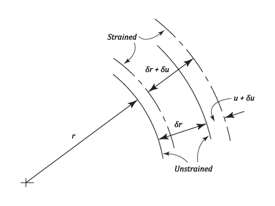
 is constant( i.e. it is independent of
  = Constant
This result coupled with the equilibrium equation (6) allows all the other equations to be obtained.
The majority of numerical problems can be solved by the application of equations (8) and (9). However, some examples may require the use of a general formula for
= Constant
This result coupled with the equilibrium equation (6) allows all the other equations to be obtained.
The majority of numerical problems can be solved by the application of equations (8) and (9). However, some examples may require the use of a general formula for  in terms of the dimensions and the external pressures.
Given an internal pressure of
in terms of the dimensions and the external pressures.
Given an internal pressure of  (Internal diameter
  , external pressure
  , and diameter
  ), it then follows that the radial stresses at these surfaces must be equal to the applied pressures and equation (8)can be written as:
&space;-&space;2\pi&space;r}{2\pi&space;r}&space;=&space;\frac{u}{r}) Thus the Radial Shift at an unrestrained radius of
Thus the Radial Shift at an unrestrained radius of  will be
 . The Radial Strain = Increase in
  /
/  in the limit.
The derivation of the Strain Equations appears in " Engineering Materials/Compound Stress and Strain". Using the equations given:-
It is necessary to eliminate
in the limit.
The derivation of the Strain Equations appears in " Engineering Materials/Compound Stress and Strain". Using the equations given:-
It is necessary to eliminate ) This equation can now be differentiated w.r.t.
This equation can now be differentiated w.r.t. \left(\frac{df_2}{dr}&space;\right)&space;+&space;\left(\frac{1}{m}&space;\right)\left(\frac{dp}{dr}&space;\right)&space;&space;\right]) From Equation (3) the above equals:
From Equation (3) the above equals:  Collecting Terms:
Differentiating equation (1) and since
Collecting Terms:
Differentiating equation (1) and since \left(\frac{df_1}{dr}&space;-&space;\frac{dp}{dr}&space;\right)) Substituting this into equation (4)
Substituting this into equation (4)
\left(1&space;+&space;\frac{1}{m}&space;\right)&space;+&space;r\left(1&space;-&space;\frac{1}{m^2}&space;\right)\left(\frac{df_1}{dr}\&space;\right)&space;+&space;\left(\frac{r}{m}&space;\right)\left(1&space;+&space;\frac{1}{m}&space;\right)\left(\frac{dp}{dr}&space;\right)&space;=&space;0) This can be reduced to:
Equilibrium Equation (Radially)
This can be reduced to:
Equilibrium Equation (Radially)
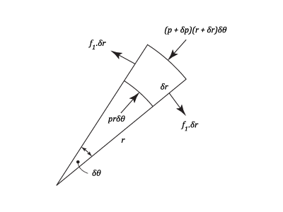
(r&space;+&space;\delta&space;r)\times&space;\delta&space;\theta&space;&space;-&space;pr\delta&space;\theta&space;&space;=&space;0) In the limit
In the limit  , and neglecting the products of small quantities the above equation reduces to:
Subtracting Equation (6) from (5)
, and neglecting the products of small quantities the above equation reduces to:
Subtracting Equation (6) from (5)
\left(\frac{df_1}{dr}&space;\right)&space;+&space;\left(\frac{r}{m}&space;\right)\left(\frac{dp}{dr}&space;\right)&space;-&space;r\left(\frac{dp}{dr}&space;\right)&space;=&space;0)
 Integrating:
where
Integrating:
where  = Constant
Subtracting equation (7) from (6)
= Constant
Subtracting equation (7) from (6)
 or
or }{dr}\;=&space;-&space;2a)
}{dr}&space;=&space;-2ar) Integrating,
Integrating,  Where
Where  and
and  Putting equation (8) in (7)

^2&space;+&space;d_1^2}{(d_1&space;+&space;2t)^2&space;-&space;d_1^2}&space;\right)\times&space;p_1=&space;\left(\frac{2(d_1/t)^2&space;+&space;4(d_1/t)&space;+&space;4}{4(d_1/t)&space;+&space;4}&space;\right)) If the ratio of
If the ratio of  then:
then: \times&space;p_1) Which is 11% higher than the mean value given by
Which is 11% higher than the mean value given by  And if the ratio is 20, then
  which is 5% higher than
  internal diameter.
Find the thickness required to withstand an internal pressure of
internal diameter.
Find the thickness required to withstand an internal pressure of  The maximum Tensile Stress is limited to
  and the maximum Shear Stress to
 is the external diameter, then the maximum tensile Stress is the hoop Stress at the inside.
Using equation (10),
is the external diameter, then the maximum tensile Stress is the hoop Stress at the inside.
Using equation (10), \times&space;4)
 From which,
  The maximum Shear Stress is half the "Stress difference" at the inside. Thus using equation (11)
\times&space;4) From which as before,
From which as before,  Therefore, The Thickness =
 &space;=&space;3.72\;in.)
in tension and there is NO Strain hardening; i.e., it is an ideal elastic material.
 and integrating gives :
 + Constant
If the radial Stress is
+ Constant
If the radial Stress is  at the outer radius of the plastic zone
  .
Then Constant =
.
Then Constant =  And using equation (13), the Hoop Stress is given by:
 bore and with a wall thickness of
  , is subjected to an internal pressure sufficient to cause yielding in two thirds of the metal.
Calculate this pressure and show the variation of Stresses across the wall.
What are the pressures required for initial yield and complete yield? Assume that yield occurs due to maximum shear stress and neglect Strain Hardening. In simple Tension
, is subjected to an internal pressure sufficient to cause yielding in two thirds of the metal.
Calculate this pressure and show the variation of Stresses across the wall.
What are the pressures required for initial yield and complete yield? Assume that yield occurs due to maximum shear stress and neglect Strain Hardening. In simple Tension 
 and
and  Thus,
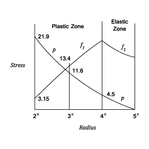
Thus, &space;=&space;21.9\;tons\;in.^{-2}) And using equation (17)
And using equation (17)
25&space;=&space;4.5\;tons\;in.^{-2})
 Using Equation (19), at
  the Hoop Stress is given by:
&space;=&space;3.15\;tons\;in.^{-2}) At
At 
 In the elastic zone, using the conditions that
  and
and  for a tube of inner and outer radii of 4 in. and 5 in., that the Hoop Stress is given by:
\times\left(\frac{r_2^2}{r^2}&space;\right)\times&space;p_2) At
At 
\times&space;4.5&space;=&space;20.5\;tons\;in.^{-2}) At
At 
\times&space;4.5&space;=&space;16\;tons\;in.^{-2}) The variation of these Stresses in the two zones is shown on the following Diagram.
The variation of these Stresses in the two zones is shown on the following Diagram.
\times&space;25&space;=&space;10.5\;tons\;in.^{-2}) And the pressure for a complete yield is found from equation (22)
And the pressure for a complete yield is found from equation (22)

 outside diameter. The compound tube is to withstand an internal pressure of
  and the shrinkage allowance is to be such that the final maximum stress in each tube is to be the same.
Calculate this stress and show in a diagram the variations of Hoop Stress in the two tubes. What is the initial difference of diameters prior to assembly ?
and the shrinkage allowance is to be such that the final maximum stress in each tube is to be the same.
Calculate this stress and show in a diagram the variations of Hoop Stress in the two tubes. What is the initial difference of diameters prior to assembly ?

 be the common radial pressure due to shrinkage.
Substituting in equation (9)
be the common radial pressure due to shrinkage.
Substituting in equation (9)
 At the inside
  Solving these two equations for
  and
and  :
:
 And
Now using equation (9)
The Maximum Hoop Stress =
And
Now using equation (9)
The Maximum Hoop Stress =  Maximum Hoop Stress at
 At the outside
  Solving these two equations for
  And
Maximum Hoop Stress =
And Hoop Stress at
And
Maximum Hoop Stress =
And Hoop Stress at  The lines marked "Shrinkage Stress" on the diagram are sketched from the results of equations
(1) and (3). The numerical value of
The lines marked "Shrinkage Stress" on the diagram are sketched from the results of equations
(1) and (3). The numerical value of  At the outside
  Solving these two equations for
  And
And  The Hoop Stresses are:
At
The Hoop Stresses are:
At 


 Diameter.
=
Diameter.
=


 The longitudinal Stress is zero and assuming that the longitudinal strain is constant, it follows that:
 But since the Stresses cannot be infinite at the centre of the shaft,
 in diameter is to be pressed into a cast iron hub of
  Find the necessary force fit allowance and the maximum circumferential Stress in the hub.
  and Poisson's Ratio =
  for both. The coefficient of friction between the surfaces is
  .
If after assembly the shaft is subjected to an axial compressive Stress of
.
If after assembly the shaft is subjected to an axial compressive Stress of  , what is the resulting increase in the maximum circumferential Hub Stress ?


 Thus,
Thus, 
 And the decrease in the outside diameter = Hoop Strain
 \times&space;2}{30\times&space;10^6}&space;=&space;0.000297\;in.)
 Increase in inside diameter =
 \times&space;2}{15\times&space;10^6}=&space;0.00119\;in.)
 = Approximately
  If
If 
 where
where  = The Increase in Pressure
The radial and Hoop Stresses in the Shaft must also increase by the same amount since they are both equal and compressive.
Increase in the Hoop Strain at the outside of the shaft
= The Increase in Pressure
The radial and Hoop Stresses in the Shaft must also increase by the same amount since they are both equal and compressive.
Increase in the Hoop Strain at the outside of the shaft
\left(-&space;0.8&space;f_1&space;+&space;0.25\times&space;0.8f_1&space;+&space;0.25\times&space;5\right)) = The increase in ther Hoop Strain at the inside of the Hub.
= The increase in ther Hoop Strain at the inside of the Hub.
(f_1&space;+&space;0.25\times&space;0.8f_1)) Giving
Giving )

 Multiply Equation (16) by
 \left(\frac{df}{dr}&space;\right)&space;+&space;\left(\frac{1}{m}&space;\right)\left(\frac{dp}{dr}&space;\right)&space;\right]\;=&space;-&space;p&space;-&space;\frac{2f}{m}) Consider the equilibrium of a Hemisphere:
Consider the equilibrium of a Hemisphere:
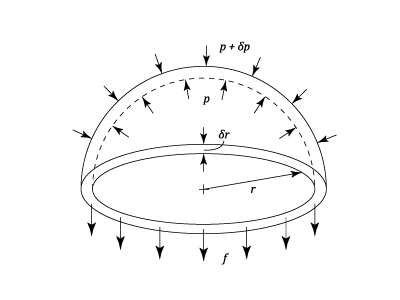
\pi&space;\left(r&space;+&space;\delta&space;r&space;\right)^2) Substituting
Substituting ) from equation (26) into equation (25)
from equation (26) into equation (25)
\left(\frac{dp}{dr}&space;\right)\left(1&space;+&space;\frac{1}{m}&space;\right)&space;+&space;r\left(1&space;-&space;\frac{1}{m}&space;\right)\left(\frac{df}{dr}&space;\right)&space;+&space;\left(\frac{r}{m}&space;\right)\left(\frac{dp}{dr}&space;\right)&space;=&space;0) Which reduces to :
Which reduces to :
 Integrating,
Substituting for
Integrating,
Substituting for  from equation (27) in equation (26)
\left(\frac{dp}{dr}&space;\right)) This can be re-arranged as:
This can be re-arranged as: }{dr}\;=&space;-&space;2Ar^2) Integrating gives:
Integrating gives:
 and
and  By putting
  and
and  By combuining this result with equation (27)
If the inside and outside diameters are
By combuining this result with equation (27)
If the inside and outside diameters are  and
and  Solving these equations gives:
) And
And  From Equations (28) and (29)
\times&space;\frac{d_1^3\;d_2^3}{d^3}&space;\right)\times&space;\frac{1}{d_2^3&space;-&space;d_1^3})
\times&space;\frac{d_1^3\;d_2^3}{2d^3}&space;\right)\times&space;\frac{1}{d_2^3&space;-&space;d_1^3}) If there is internal pressure only:-
If there is internal pressure only:-
)
) The Maximum Stress is the value of
The Maximum Stress is the value of }{2(d_2^3&space;-&space;d_1^3)}) And the maximum Shear Stress,
And the maximum Shear Stress, &space;=&space;\displaystyle\frac{p_1\;.\;3\;d_2^3}{4(d_2^3&space;-&space;d^1^3)})