
Gyroscopes
Key Facts
Gyroscopic Couple: The rate of change of angular momentum ($\tau$) = $I\omega\Omega$ (In the limit).- $I$ = Moment of Inertia.
- $\omega$ = Angular velocity
- $\Omega$ = Angular velocity of precession.
An analysis of gyroscopic couples.
Introduction
Whilst Gyroscopes are used extensively in aircraft instrumentation and have been utilised in monorail trains, the everyday impact of gyroscopic forces on our lives is unappreciated and significant.
The simple example is a child's top which would not work but for the gyroscopic couple which keeps it upright. On a slightly different level, the gyroscopic couple helps us to keep a bicycle upright. It is interesting and instructive to remove a bicycle wheel from its frame, hold it by the axle, spin the wheel and then try to change the orientation of the axle. The force required to do so is considerable!
However, these gyroscopic forces are not always beneficial, and it will be shown that the effect on the wheels of a car rounding a corner are to increase the tendency for the vehicle to turn over.
Angular Displacement, velocity and Acceleration
Note: Without an understanding of Angular movement it is difficult to understand Gyroscopic Couples. For this reason the paragraph on Angular Displacement, Velocity, and Acceleration shown in "The Theory of Machines - Mechanisms", has been reproduced here.
Let:
- The line $OP$ in the diagram rotates around $O$
- Its inclination relative to $OX$ be $\phi$ radians.
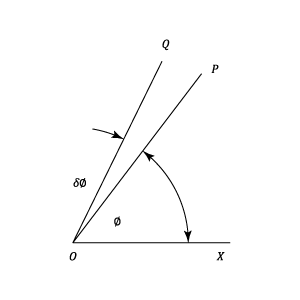
Then if after a short period of time the line has moved to lie along $OQ$, then the angle $\delta\theta$ is the Angular Displacement of the line.
Angular Displacement
In order to completely specify angular displacement by a vector, the vector must fix:-
- The direction of the axis of rotation in space.
- The sense of the angular displacement, i.e., whether clockwise or anti-clockwise.
- The magnitude of the angular displacement.
In order to fix the vector, it can be drawn at right angles to the plane in which the angular displacement takes place; say along the axis of rotation, and its length will be (to a convenient scale) the magnitude of the displacement.
The conventional way of representing the sense of the vector is to use the right-hand screw rule, i.e.,
- The arrow head points along the vector in the same direction as a right handed screw would move relative to a fixed nut.
- Using the above convention, the angular displacement $\delta\theta$ shown in the diagram would be represented by a vector perpendicular to the plane of the screen and the arrow head would point away from the screen.
Angular Velocity
Angular Velocity is defined as the rate of change of angular displacement with respect to time. As angular velocity has both magnitude and direction, it is a vector quantity, and may be represented in the same way as angular displacement.
- If the direction of the angular displacement vector is constant, i.e., the plane of the angular displacement does not change its direction, then the angular velocity is merely the change in magnitude of the angular displacement with respect to time.
Angular Acceleration
Angular Acceleration is defined as the rate of change of angular velocity with respect to time. It is a Vector quantity. The direction of the acceleration vector is not necessarily the same as the displacement and velocity vectors.
Assume that at a given instant a disc is spinning with an angular velocity of $\omega$in a plane at right angles to the screen, and that after a short interval of $\delta t$its speed has increased to $\omega + \delta\omega$.
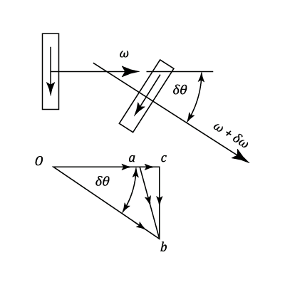
Then applying the right-hand rule:
- The angular velocities at the two instants are represented by the vectors $oa$ and $ob$.
- The change of angular velocity in a time of $\delta t$ is represented by the vector $ab$. This can be resolved into two components $ac$ and $cb$ which are respectively parallel and perpendicular to $oa$.
Hence,
- The component parallel to $oa$ is given by:$\displaystyle \alpha_T=\frac{d\omega}{dt}$
- The component perpendicular to $oa$ is given by: $\displaystyle \alpha_C=\omega\;\frac{d\theta}{dt}=\omega\times \omega_P$
Note:
- $\omega_P$ is the rate of change of direction of the vector $oa$.
- $\alpha_T$ is the rate of change of the magnitude of velocity $\omega$ of the disc.
- $\alpha_C$ is the rate at which the direction of $\omega$, and therefore the plane of the rotation of the disc, is changing.
- The total angular acceleration of the disc is the vector sum of $\alpha_T$ and $\alpha_C$.
Two particular cases should be noted:
- If the plane of rotation of the disc is constant in direction, then $\omega_P$ is zero and the component of acceleration $\alpha_C$ is zero.
- If the angular acceleration of the disc is constant in magnitude but the plane of rotation changes direction at the rate $\omega_P$ radians per second, then the angular acceleration of the disc is given by:
$\alpha_C=\omega\;\frac{d\theta}{dt}=\omega\times \omega_P$
- The direction of this acceleration vector is at right angles to the angular velocity vector and lies in the plane of motion of the velocity vector.
Gyroscopic Couple
If a uniform disc of polar moment of inertia $I$ is rotated about its axis with an angular velocity $\omega$, its Angular Momentum $I\;\omega$ is a vector and can be represented in diagram (c) by the line up which is drawn in the direction of the axis of rotation. The sense of the rotation is clockwise when looking in the direction of the arrow.
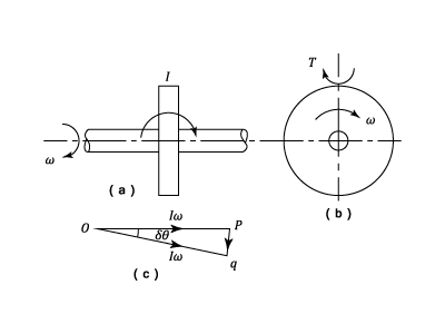
If now the axis of rotation is precessing with a uniform angular velocity $\Omega$ about an axis perpendicular to that of $\omega$, then after a time $\delta t$ the axis of rotation will have turned through an angle $\delta \theta=\Omega\,\delta t$ and the momentum vector will be $oq$.
The Gyroscopic Couple $\tau$ is given by:
$\tau$= The rate of change of angular momentum =$\displaystyle\frac{pq}{\delta t}= \displaystyle\frac{I\,\omega\,\delta\theta}{\delta t}=I\,\omega\,\Omega$ (In the limit)
- The direction of the couple acting on the gyroscope is that of a clockwise rotation when looking in the direction $pq$.
- In the limit, the direction of the couple is perpendicular to the axes of both $\omega$ and $\Omega$
- The reaction couple exerted by the gyroscope on its frame is in the reverse sense (It is advisable to draw the vector triangle $opq$ in each case).
Example 1 [imperial]
The diagram shows the Gyro unit of an aircraft instrument in which the rotor is carried in a closed casing mounted in bearings so that its axis is normally vertical but free to take up any direction.
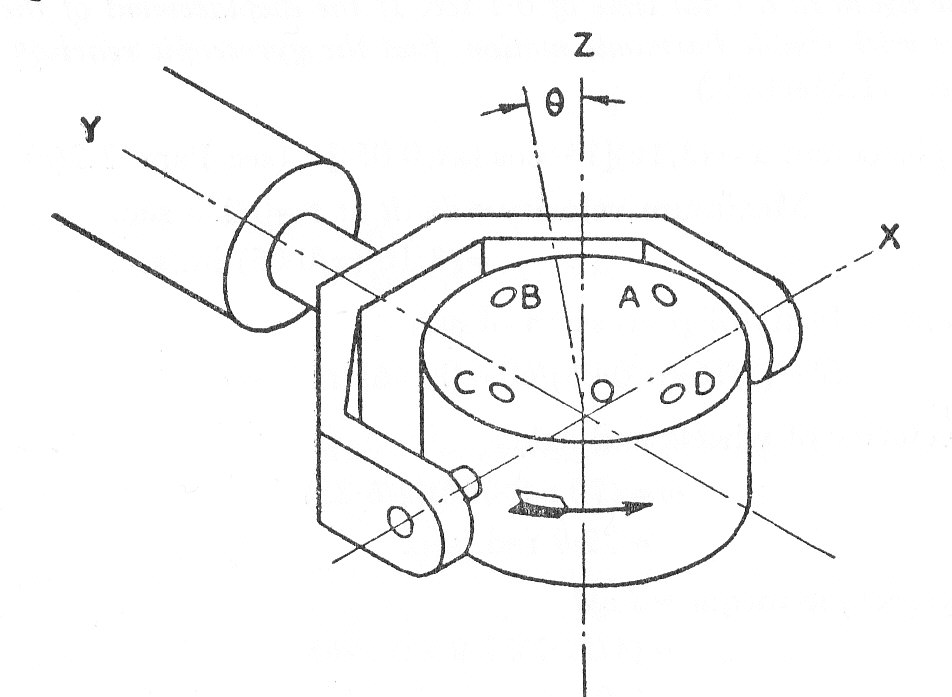
The rotor speed is maintained constant in an anti-clockwise direction, when seen from the top, by air jets inside the casing which impinge onto its slotted periphery. The used air may then leave the casing by the four orifices indicated, these are uncovered as required by gravity controlled vanes. If the rotor axis is tilted through an angle $\theta$ in the XOZ plane, explain which orifice must be uncovered so that the reaction from the jet tends to restore the axis to the vertical.
If this force is 0.0004 lb. at a distance of 0.825 in. from $O$ and the wheel is equivalent to a uniform solid disc 1.75 in. in diameter weighing 0.3 lb. and running at 9000 r.p.m., find the time required for the axle to return to the vertical is $\theta$ is $1^0$
The axis of rotation has to precess anti-clockwise about $OY$ when seen from the left. The Gyroscopic torque on the rotor must be anti-clockwise about $OX$ when seen from the right and this can be achieved by opening vent $D$.
The torque applied =$0.0004\times 0.825\;lb.in.$ $=I\;\omega\Omega=\left ( \frac{0.3}{32.2\times12}\times \frac{1.75^2}{8} \right )\times \left ( \frac{9000\times 2\pi}{60} \right )\;\Omega$
Re-arranging to give the angular velocity of precession gives:-
$\Omega=\frac{0.0004\times 0.825\times 32.2\times 12\times 8}{0.3\times 1.75^2\times 300\pi}=0.00118\;rad./sec.$
The time to precess $\;1^0=\displaystyle\frac{1}{57.3\times 0.00118}=14.8\; sec.\;\;\;\;\;\;(1^0=\displaystyle\frac{1}{57.3}\;radians)$
- The time required is $14.8\; sec.$
Example 3 [imperial]
A pair of flanged wheels 4 ft. in diameter, mounted on an axle, roll along rails spaced 5 ft. apart and at the same level and around a curve of 500 ft. mean radius, at a speed of 40 m.p.h. Each wheel is assumed to be a thin disc weighing 600 lb.
Determine the vertical force between each wheel and the rail allowing for both centrifugal and gyroscopic effects and also the horizontal force assuming this to be at the outer rail.
The angular velocity of the wheels =$\left ( \displaystyle\frac{40\times 88}{60} \right )\times \displaystyle\frac{1}{4\pi}\times 2\pi=29.3\;rad./sec$
The velocity of precession =$\left ( 40\times\displaystyle\frac{88}{60} \right )\times \displaystyle\frac{1}{500}\times \displaystyle\frac{2\pi}{2\pi}=0/1175\;rad./sec.$
The Gyroscopic reaction torque =$\left ( 2\times \displaystyle\frac{600}{32.2}\times \displaystyle\frac{4^2}{8} \right )\times 29.3\times 0.1175=257\;lb.ft.$ (Tending to lift the inside wheel)
i.e. clockwise about $qp$ as shown in the diagram.
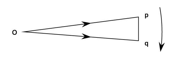
The vertical reaction at each wheel due to the gyroscopic effects =$\displaystyle\frac{275}{5}= 51.4lb.$
which is positive at the outside wheel and negative at the inside.
The centrifugal force =$M\;r\;\Omega^2=\displaystyle\frac{1200}{32.2}\times 500\times 0.1175^2=257\;lb.$ (At axle height)
This produces an equal horizontal reaction at the outside rail and a couple of $257\times 2=514\;lb.ft.$which tends to over turn the wheels. This is balanced by vertical reactions at each wheel of $\displaystyle\frac{514}{5} =102.8 lb.$ These are positive at the outside and negative at the inside.
Hence the total vertical reaction at the inside wheel is:
$600$ (weight)- $51.4$(gyroscopic)-$102.8$(centrifugal)=$446\;lb.$
$600$ (weight) +$51.4$(gyroscopic)+$102.8$(centrifugal)=$754\;lb.$
The horizontal force at the outer rails = the centrifugal force = 257 lb.
Example 4 [imperial]
The turbine rotor of a ship weighs 6 tons and has a radius of gyration of 19.5 in. It rotates at 1800 r.p.m. clockwise when looking forward from the stern.
Determine the gyroscopic effects set up if:
- a) The ship , when traveling at 15 knots, steers to the left in a curve of 200 ft. radius.
- b) The ship is pitching and the bow is descending with its maximum velocity. The pitching is simple harmonic, the periodic time is 20 sec. and the total angular movement between extreme positions is $10^0$
- c) The ship is rolling and at a certain instant has an angular velocity of 0.02 radians per second clockwise when looking from the stern.
In each case explain clearly how you determine the direction in which the ship tends to move as a result of the gyroscopic action.
Note One ton = 2240 lb. : One Knot = one nautical mile per hour = 6080 ft. per hour.
$I=Mk^2=\frac{6\times 2240}{32.2}\times\left ( \frac{19.5}{12} \right )^2=1100\;slug-ft^2$ $\omega=1800\times \frac{2\pi}{60}=188\;rad./sec.$
- a)
The linear velocity =$15\times \displaystyle\frac{6080}{3600}=25.3\;ft./sec.$
The precessional velocity = $\displaystyle\frac{25.3}{200}=0.127\;rad./sec.$
The gyroscopic reaction torque, $\tau=1100\times 188\times 0.127=26,300\;lb.ft.$
In the following diagram $op$ and $oq$ represent the angular momentum, over a short interval of
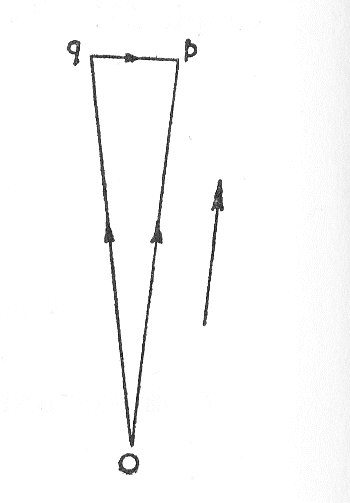
time as the ship turns left. i.e. a clockwise rotation. The direction of the reaction couple is clockwise about $qp$ i.e. looking from the inside of the curve, and will tend to lif the bows.
- b)
The angle of pitch at time $t$ =$\displaystyle\frac{5}{57.3}\times \sin\displaystyle\frac{2\pi\; t}{20}$
Differentiating and equating to zero for the maximum velocity of pitch.
$\hat{v}=\frac{5}{57.3}\times \frac{\pi}{10}=0.0274\;rad./sec.$ $\therefore \;\;\;\;\;\;\tau=110\times 188\times 0.0274=5650\;lb.ft.$
If $op$ and $oq$ are now taken to be in a vertical plane with $oq$ below $op$ ( bows descending), the gyroscopic effect is clockwise about $qp$ (i.e. looking vertically upwards) tending to turn the ship to the left.
- c)
None, since the axes of roll and the rotor are the same.