Torsion
This section examines the relationship between torsional forces; shear strain and polar moments of inertia
You're viewing an older version of this page (#3855). View the current version.
Circular Shafts
When a pure torque acts upon a shaft, shear stresses will be set up which act in directions perpendicular to the radius at all points.
The complimentary shear stresses on longitudinal planes will cause the distortion of filaments
which were originally in the longitudinal direction. Assume that the points lying on a radius
before twisting will remain on that radius and that the angle of twist is uniformly
over the length of the shaft.
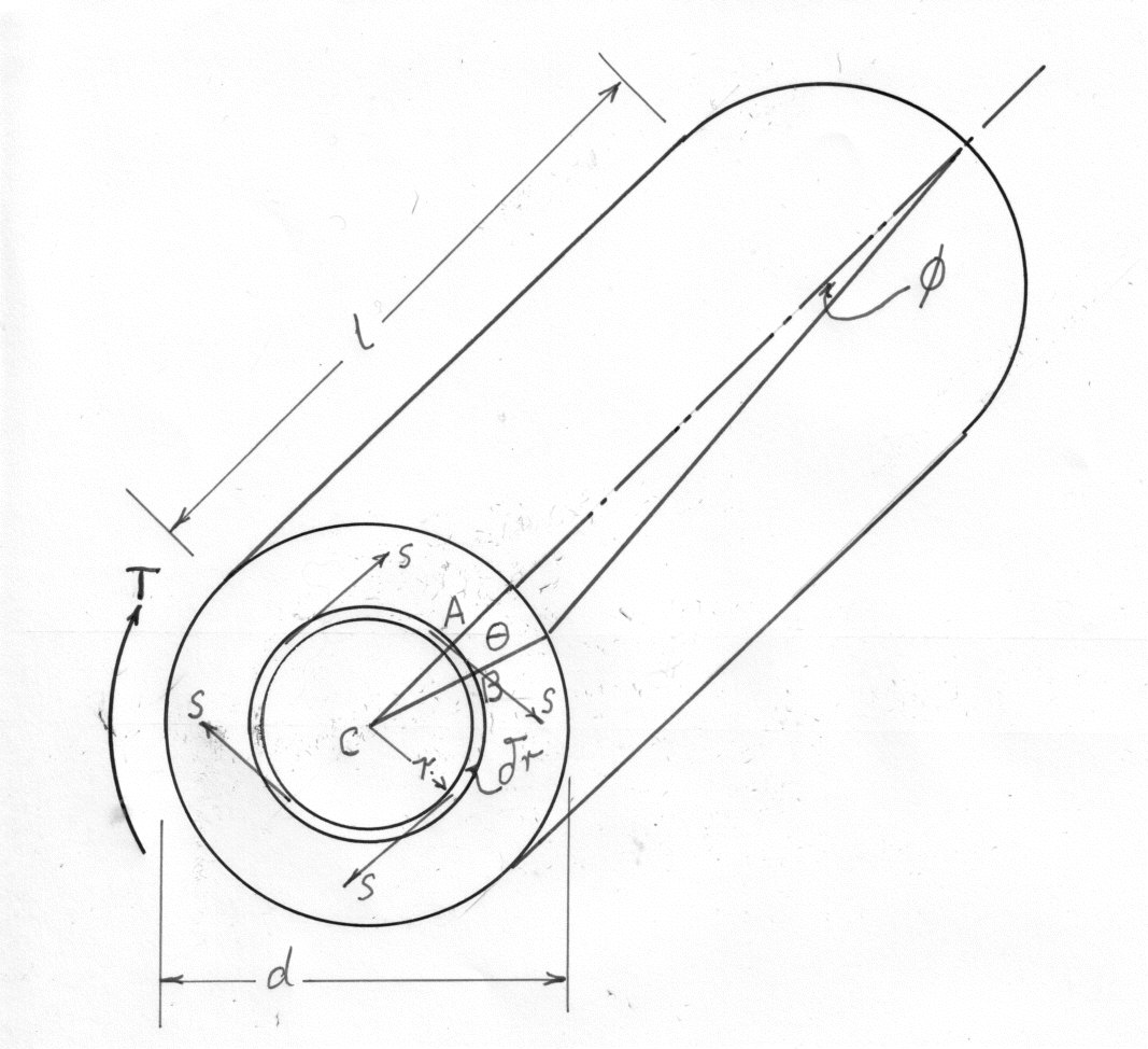
The diagram shows the shear strain of elements which are at a distance r from the axis (
When T is constant
is constant) so that the line originally OA has twisted to OB and the
angle ACB is now
, the relative angle of twist for cross sections a distance l apart .
But
From the above two equations
The torque T can be equated to the sum of the moments of the tangential stresses on the element
substituting from equation (3)
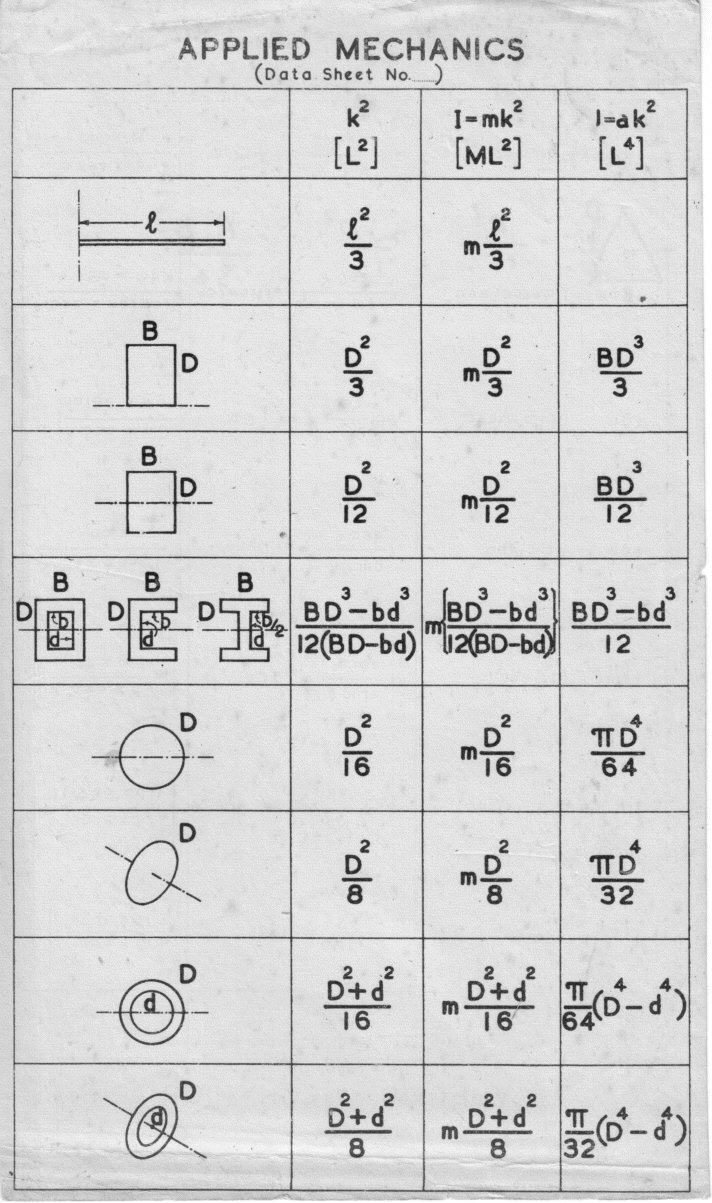
But J, the polar moment of inertia which
Combing equations (3) and (6)
This equation shows that the shear stress is proportional to the radius (the equation is analogous to that proven in the section on linear bending stress.)
For a solid shaft and for a hollow shaft
The maximum stress for a solid shaft
and for a hollow shaft
Torsional stiffness ;is defined as torque per radian twist. i.e.
Example 1
Compare the weights of equal lengths of hollow and solid shaft to transmit a given torque for the same maximum shear stress, if the inside diameter is 2/3 of the outside.
We know that
for a solid shaft:
and
or
If the torques on both shafts are equal
The ratios of equal lengths =
Thus the ratio of the weight of the hollow shaft to that of the solid shaft
The ratio of the weight of the hollow shaft to that of the solid shaft is 0.642.
Shafts of varying diameter
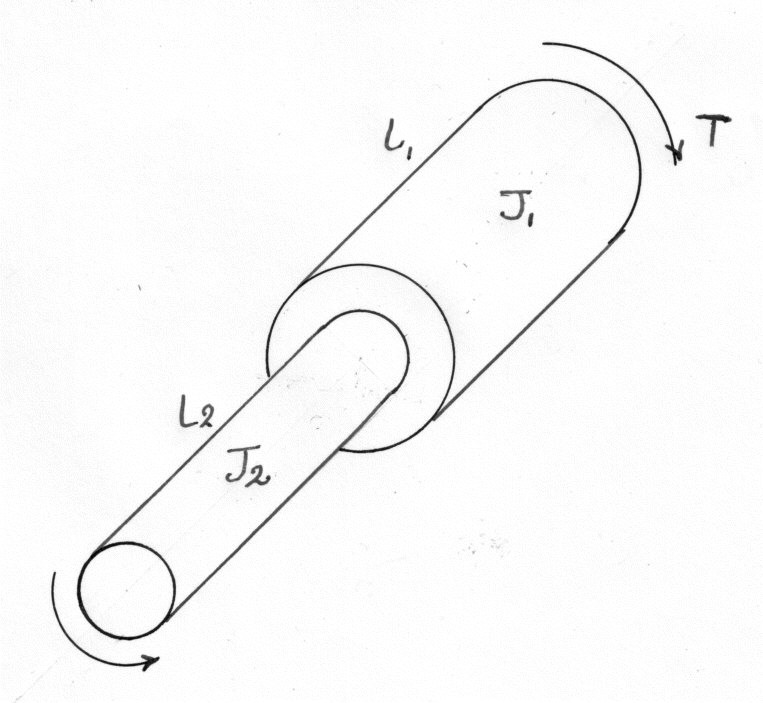
Angle of twist in larger shaft =
and for the thinner =
If the shafts are made of the same material
Composite shafts
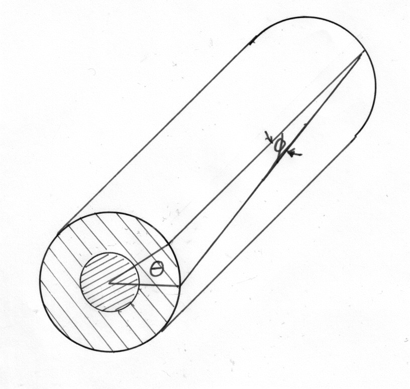
The angle of twist per unit length is the same for both materials.
From which
Combined Bending and Twisting.
This occurs frequently in practice when a shaft is subjected to both a bending and inertia forces. Stresses are set up due to gravity; torque and shear forces although the latter is usually unimportant since its maximum value occurs at the neutral axis where the bending stress is zero.
For the purposes of design it is necessary to calculate all the principle stresses( maximum shear stress; shear strain energy etc) so that these can be used to compare them with the criterion of failure.
If is the greatest bending stress and s is the greatest shear stress due to bending
then:
For loading in the vertical plane, these stresses will occur together at the end of a vertical diameter, since there is no normal stress on longitudinal planes of the shaft, they are maximum principle stress.
Note: that is the equivalent bending moment that would produce the same maximum stress.
The maximum shear stress q is given by;-
and this is the same shear stress as would be produced by a pure torque of magnitude
Example 1 [imperial]
A flywheel weighing 1200lb. is mounted on a shaft 3in. in diameter and midway between two bearings 24in. apart. If the shaft is transmitting 40 h.p. (1 h.p. = 550 ft.lb./sec)Calculate the maximum shear stress at the end of a vertical and horizontal diameter in a plane close to the flywheel.
At the ends of a vertical shaft
thus on the "tension" side of the shaft the principle stresses are 3250 lb./sq.in. in tension and 528 lb./sq.in. compression. On the "Compression side the principle stresses are 3250lb./sq.in. in compression and 528lb./sq.in. in tension.
The maximum shear stress is given by:
At the end of a horizontal diameter the bending stress is zero and the torsional shear stress has a value.
This is a pure shear stress and the principle stresses are , the maximum shear stress being 1320 lb./sq.in.
The maximum shear stress is 1320 lb./in\^2.
Strain Energy in Torsion.
When a shaft of length l is gradually twisted through an angle under the influence of
a Torque T. The work done (equals the total strain energy U) is given by:-
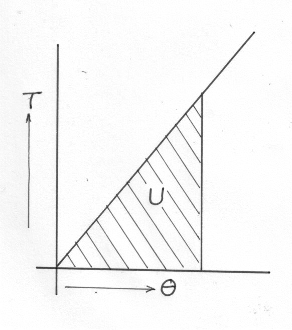
Substituting value for T and
in equations (35)gives:-
This gives the total strain energy over the whole shaft. The shear stress varies from zero at the
axis to at the outside.
For a hollow tube :-
Example 1
A hollow shaft subject to a pure torque,attains a maximum shear stress of f. Given that the strain energy is . Calculate the ratio of shaft diameters.
We know that \f[\therefore\;\;\;U = \left(\frac{s_{max}^2}{4C} \right)\;X\;\left(\frac{(D^2\,+\,d^2)}{D^2} \right)\;X\;volume\f]
\f[\frac{U}{Volume} = \left(\frac{f^2}{4C} \right)X\left(\frac{D^2 + d^2}{D^2} \right) = \frac{f^2}{3C}\;\;\;(given)\f]
The ratio is, = 1.732
Moments of Inertia