
Springs
Definitions
- D = Mean coil diameter
- d = Wire diameter
- n = Number of coils
An analysis of the common types of engineering springs.
You're viewing an older version of this page (#3895). View the current version.
Introduction
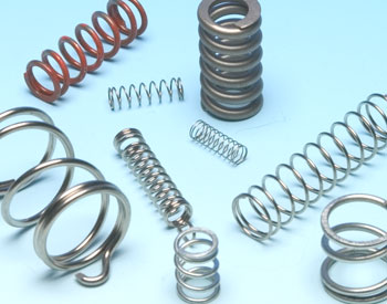
Springs are load bearing elastic objects that are used to store and transfer mechanical energy. They are usually made from a low alloy, medium or high carbon steel. Their relatively high yield strength allows them to return to their original shape and size after a temporary deformation. There are several types of springs, including helical springs, flat springs and torsion springs among others. Each of these types is suited to its own specific application, however, they are all constructed from a pliable / resilient material that can withstand a certain degree of deformation without fracture or failure.
In engineering applications springs are often used for their compression or load-bearing ability, as well as for dampening out the effects of shock or impact loads.
Closed-Coiled Helical Springs
1 - Under Axial Load, W
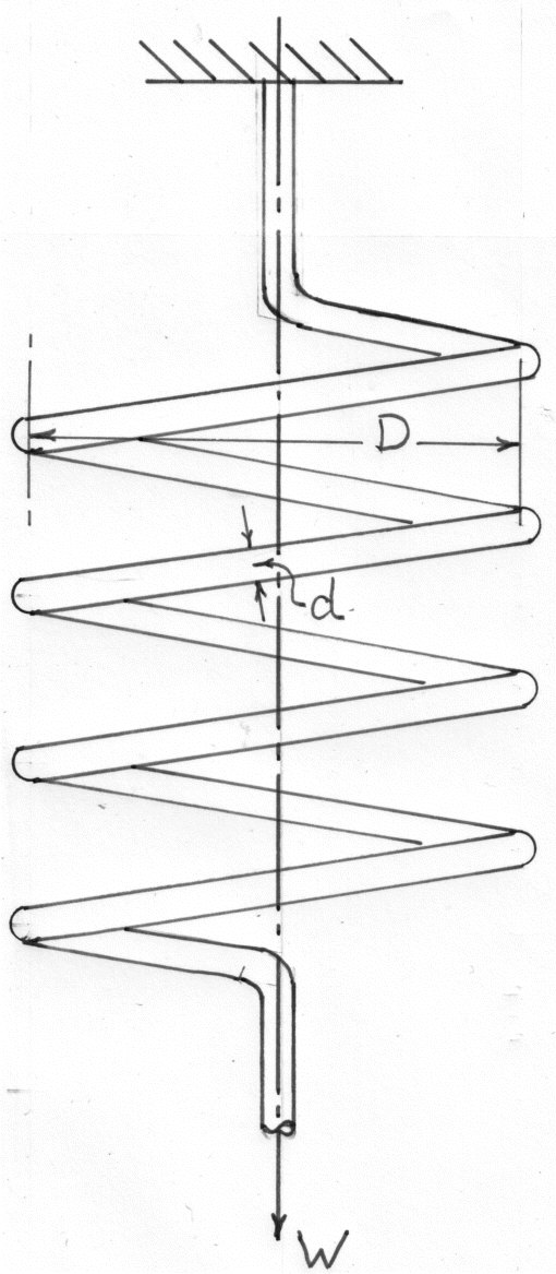
As the angle of the helix is small, the action on any cross section is approximately a pure torque and the effects of bending and shear can be neglected. The value of the torque is given by:
The wire can therefore be considered to being twisted like a shaft. If is the total angle of twist along the wire, and x is the deflection of W along the axis of the coil, then
and
Applying the formula for torsion of shafts and making the above substitution
or
The spring stiffness
The strain energy
Which by substitution in terms of from equation (7) can be reduced to:
2- Under Axial Torque Load, T
This will produce approximately a pure bending moment of magnitude T at all cross sections. The total strain energy is therefore given by:
But if T causes a rotation of one end of the spring through an angle about the axis relative to the other end, then:
Substituting this in equation (#11)
Example 1 [imperial]
A close-coiled helical spring is to have a stiffness of 5lb./in.in compression, with a maximum load of 9 lb. and a maximum shear stress of 18,000lb./in\^2. The solid length of the spring(i.e. coils touching) is 1.8in. Find the wire diameter; mean coil radius and the number of coils. .
We know that,
Again,
Substituting from equations(5) and (6) in equation (3)
Substituting this value in equation (3)
i.e. mean coil radius =
And from equation (5) the number of coils,
Wire diameter, d = 0.1145 in
Mean coil radius = 0.56 in
The number of coils, n = 15.7
Example 2 [imperial]
A composite spring has two close-coiled springs connected in series; each spring has twelve coils and a mean diameter of 1 in. Find the wire diameter in one if the other is 0.1 in. and the stiffness of the composite spring is 4 Lb./in.
Estimate the greatest load that can be be carried by the composite spring and the corresponding extension for a maximum shear stress of 12tons/in\^2
For springs in series the load is common to both and the total extension is the sum for each .
So
Or
Using equation (8)
from which it can be shown that d = 0.084 in. Using the equation , the limiting load will be in the spring with the smallest diameter wire.
and the total extension
Wire diameter, d = 0.084 in
The greatest load carried by the composite spring, W= 6.26 lb
The corresponding extension for maximum shear stress = 1.56 in
Example 3 [imperial]
A close-coiled helical spring of circular cross section extends 1 in. when subjected to an axial load W and there is an angular rotation of when a torque T is independently applied about the axis. If
is the mean coil diameter, show that
Determine Poisson's ratio if A load of 55lb. extends the spring by 5.4in. and a Torque of 30lb.in. produces an angular rotation of 60 degrees.
We know that
And from equation (14)
Since here
Poisson's ratio,
Open-coiled helical spring.
Let be the angle of the helix, then the length of the wire
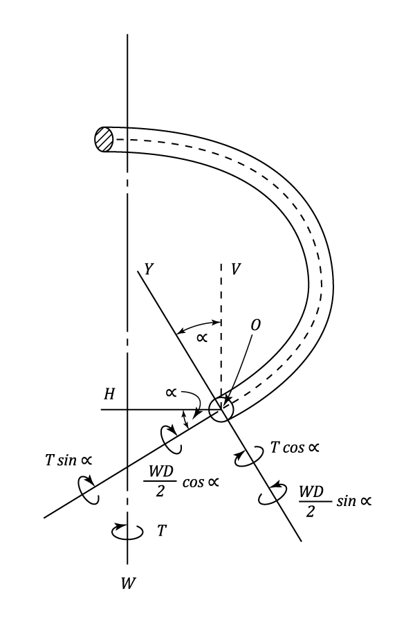
In the diagram OX is the polar axis (axis of twisting) at any normal cross section, and is inclined at an angle to the vertical OV. All the axes OX,OY,OH,and OV are in the vertical plane, which is tangential to the helix at O.
If now an axial load W and an axial torque T are applied to the spring, the latter tending to increase the curvature, the actions at O are couples WD/2 about H and T about OV (the effect of the shearing force W may be neglected).
Resolving these couples about the axis OX and OY the combined twisting couple
and the combined bending couple
both of which tend to increase the curvature.
The total strain energy due to bending and twisting is given by:
Using Castiliano's Theorem, the axial deflection and the axial rotation
. The general case can be derived from the above expressions but usually the loading is either W only or T only and the solution to these cases is given below.
1 - Under Axial Load Only, W
2 - Under Axial Torque Only, T
Example 1 [imperial]
An open coiled spring is made having ten turns wound to a mean diameter of 4.5 in. The wire diameter is 3/8 in. and the coils make an angle of 30 degrees with a plane perpendicular to the axis of the coil.
Find the axial extension when subjected to a load of 20 lb. and find the angle through which the free end will turn with this load if free to rotate.
Axial extension
Angle of rotation of free end.
Axial extension = 0.672 in
Angle of rotation of free end =
Leaf Springs
This type of spring was universally used on cars, lorries, and railway trucks. Whilst the introduction of independent suspension has reduced the automotive use, leaf springs are still in common use. The spring is made up of a number of leaves of equal width but varying length, placed in laminations and loaded as a beam. There are two main types. The "Semi-elliptic" is simply supported at both ends and loaded at it's centre whilst the quarter-elliptic is arranged as a cantilever.
Semi-Elliptical Type
In order to develop a simplified theory, it is assumed that the ends of each leaf (where they extend beyond their neighbour)are tapered uniformly to a point. It is also assumed that the "pack" is complete and that the shortest leaf is diamond shaped. These assumptions are not realised in practice. The main leaf must by necessity retain it's full width where it is supported. These slight departures from design do not seriously affect the the theory.
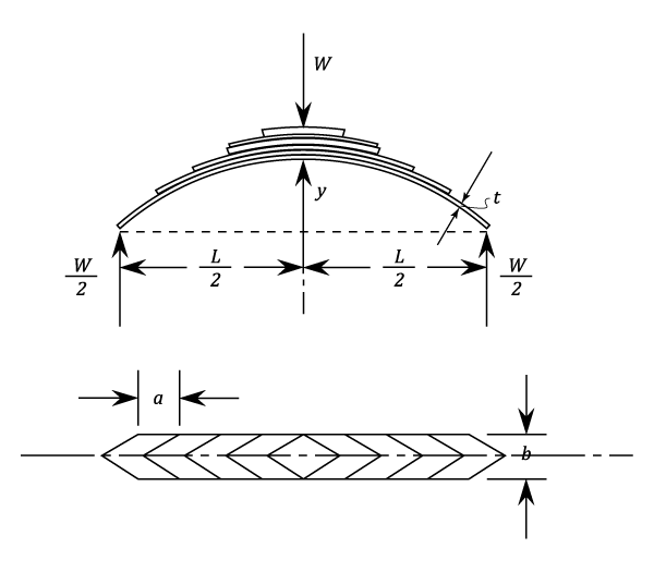
Let,
- l = span ( assumed constant)
- b = width of leaves
- t = thickness of leaves
- W = central load
- y = rise of crown above the level of the ends
- n = The number of leaves in the spring
If the leaves are initially curved to circular arcs of the same radius , contact between the leaves will only take place at their ends and consequently the loading of any one leaf will be as shown in the following diagram:
Over the central portion both M and I are constant, whilst over the end section both M and I are proportional to the distance from the end. Consequently over the whole leaf M/I is constant, but
(see "Bending of curved bars")
Since is assumed to remain constant, the radius of curvature R in the strained case must be the same for all leaves and contact continues to be through the ends only.
Friction between the leaves is ignored and it is assumed that each leaf is free to slide over it's neighbour. And since they all maintain the same radius of curvature, they can be imagined to be arranged side by side to form a curved beam of constant depth and varying width (as shown)
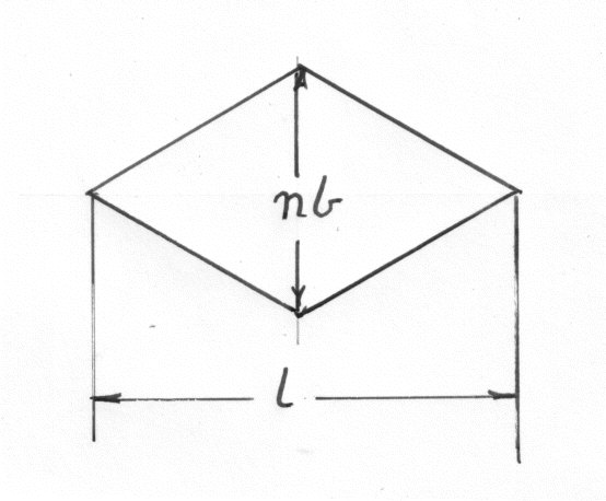
As the bending moment for the equivalent section is directly proportional to the distance from either end, and I also varies uniformly, it can be seen that the spring is equivalent to a beam of uniform strength ( i.e. the beam has the same maximum strength at all sections).
Now consider any convenient cross section. In the following analysis the central section has been used.
Using equations of a circle
and treating y as small compared to R
Rewriting equation (#65)
The deflection is given by:
The load required to straighten the load is called the "Proof Load" and is given by:
The maximum bending stress is given by:
Quarter-elliptic type
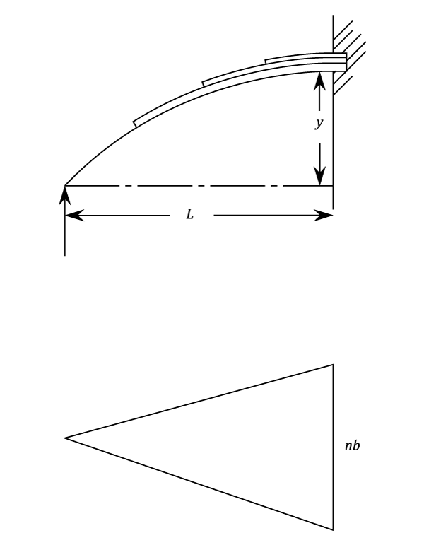
The analysis is similar to to that used above. In this case the equivalent plan section varies from zero to nb at the fixed end, and the other values at this end are:
Substituting in equation (#65)
or
and
Example 1 [imperial]
A laminated steel spring , simply supported at the ends and centrally loaded, with a span of 30 in., is required to carry a proof load of 0.75 tons whilst the central deflection is not to exceed 2 in. The bending stress must not exceed 25tons/in\^2.. Plates are available in multiples of for thickness and
for width.
Determine suitable values for width; thickness; number of plates and calculate the radius to which the plates should be formed. Assume that the width is twelve times thickness and that
We know
Now,
Dividing (3) by (7)
and
From equation (7)
The actual deflection under the proof load of 0.75 tons.
since the spring is now straight, the initial radius of curvature is given by:-
Width,
Thickness,
Number of plates = 11
The radius to which the plates should be formed,