
Water Turbines
This section covers the analysis of water turbines and the selection of turbines for a particular application
You're viewing an older version of this page (#3361). View the current version.
WATER TURBINES
The Government and the EU demands that we reduce the quantity electricity from fossil fuels. The alternatives such as wind and wave power are Dependant on climatic conditions and tidal power has great difficulty in generating continually over a 24 hour period. In contrast Hydro electricity a reliable form of renewable energy. Water turbines are highly efficient and easily controlled to provide power as and when it is needed. In addition, currently the only system available to store large quantities of electrical power, is pumped storage.
IMPACT OF WATER ON VANES
1. General - (to find force; work done; efficiency [ ]; etc.)
a) Find the mass of liquid/sec. striking the vanes ( slugs/sec or kilograms/sec)
b) Find the change in absolute (or relative) velocity of the liquid in the required direction. (ft/sec. or meters/sec.)
c) Force on the vane in this direction ( Newton's second Law) equals mass/sec X change of velocity. ( slugs/sec X ft/sec = lb. or kg/sec X mtr./sec = Newtons)
d)The vane exerts an equal and opposite reaction on the the liquid and the supply nozzle. (Jet reaction)
e)Work done / sec. by the liquid on the vane is the vane velocity X force on plate in the direction of the velocity. (ft.lb./sec. or Watts)
f) Horse Power output =
g) Efficiency; = Output Power/ Input power from jet
IMPACT OF WATER ON VANES
1. General - (to find force; work done; efficiency [ ]; etc.)
a) Find the mass of liquid/sec. striking the vanes ( slugs/sec or kilograms/sec)
b) Find the change in absolute (or relative) velocity of the liquid in the required direction. (ft/sec. or meters/sec.)
c) Force on the vane in this direction ( Newton's second Law) equals mass/sec X change of velocity. ( slugs/sec X ft/sec = lb. or kg/sec X mtr./sec = Newtons)
d)The vane exerts an equal and opposite reaction on the the liquid and the supply nozzle. (Jet reaction)
e)Work done / sec. by the liquid on the vane is the vane velocity X force on plate in the direction of the velocity. (ft.lb./sec. or Watts)
f) Horse Power output =
g) Efficiency; = Output Power/ Input power from jet
2 Series of moving plates
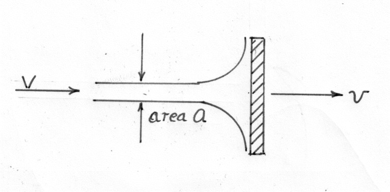
Assume that the water leaves the plates tangentially
The weight of water hitting the plates per second = W = waV
N.B. For a single plate the weight of water per second striking the plate is wa(V-v)
The change of velocity = (V - v)
The input = the Kinetic energy of the jet
and the value of the maximum efficiency
3 A single plate inclined to the jet.
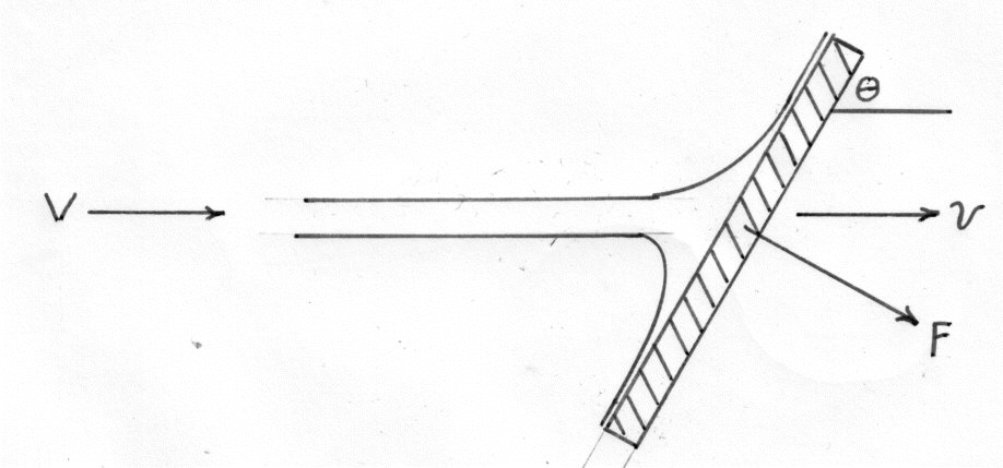
Neglecting friction and assuming that the water leaves the plate tangentially, the resulting force will be normal to the plate.
The weight of water striking the plate per second will be, as before, given by:-
Change of velocity normal to the plate =
Normal force on plate F =
Component of F in the direction of v =
Stationary Curved Vanes
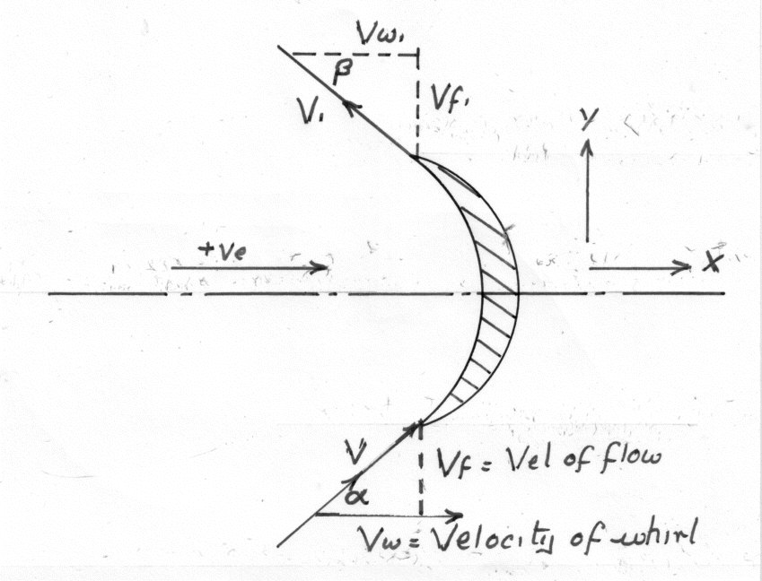
Force in the direction of x =
N.B. is negative.
For a semi circular blade both are zero and neglecting friction the force is twice that of a corresponding flat plate.
Force in direction y =
A Series of Moving Curved Vanes.
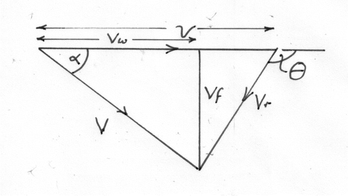
The following symbols are used in the construction of velocity triangles.
( The arrows of v and must follow each other round the triangle)
The suffix 1 refers to he outlet triangle.
are the inlet and outlet angles of absolute velocity (i.e.Jet0
are the inlet and outlet angles relative to the blade velocity.
a) Axial Flow Turbine
1) Low Speed
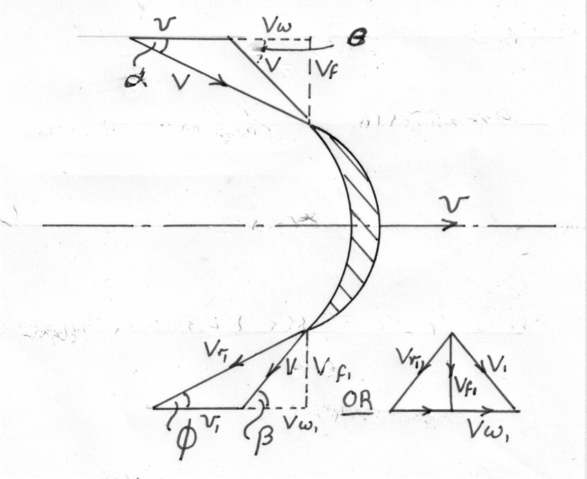
2) High Speed
The outlet triangle remains the same but the inlet triangle is now:-
Note
b) Pelton Wheel ( Circumferential )
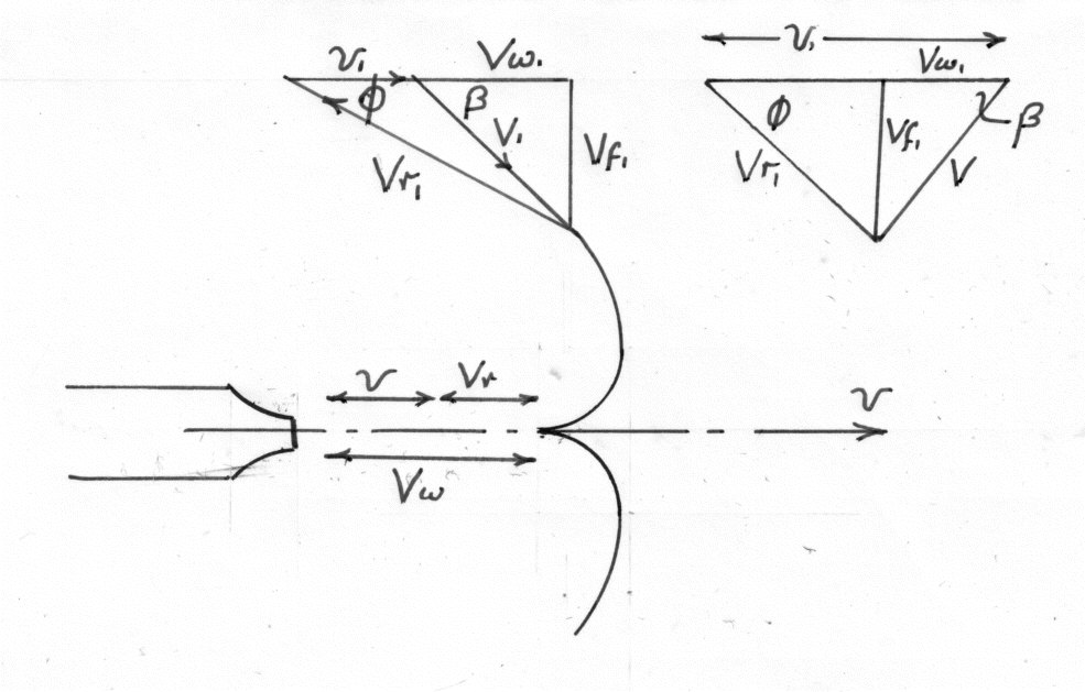
The two velocity triangles are for low and high flow. The inlet triangle is a straight line.
For both types of flow (a and b)
Where H is the head behind the nozzle and is the Velocity coefficient.
Force on the vanes = mass of water/second X Change in velocity
Work done on the vanes = Force X Velocity
For a Pelton Wheel Only.
For the maximum at a given head and blade angle
Which occurs when v = V/2 i.e. The bucket speed is half the jet speed. This is a theoretical figure and in practice, due to frictional losses, the maximum efficiency is when
Example
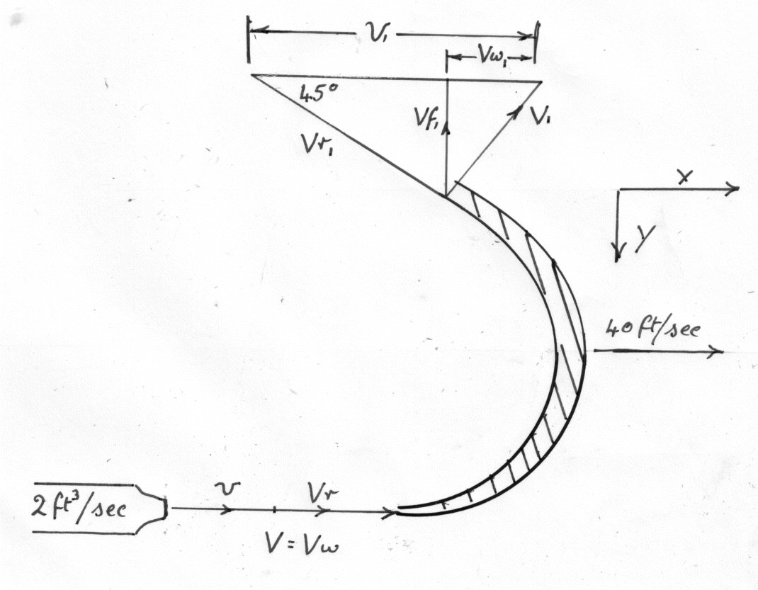
The diagram shows a section of a Pelton wheel which has a 2 in. Diam. Jet which produces 2 cubic ft. of water per second. The blade speed is 40 ft/sec and due to friction . ( 1 cubic foot of water weighs 62.4 lbs. and g = 32.2 ft/s
To find the force in the X direction.
From the outlet triangle
In the X direction the Force on the vanes = mass of water X change of velocity
Force on vanes in the Y direction =
The resultant is at
Work done per second on the vanes = The force in the X direction times blade velocity
The Kinetic energy supplied by the jet per second
Turbine with Curved Vanes and an Inward Radial Flow ( Francis or Gerard Turbine )
The following diagram shows the velocity triangles for both low and high speed
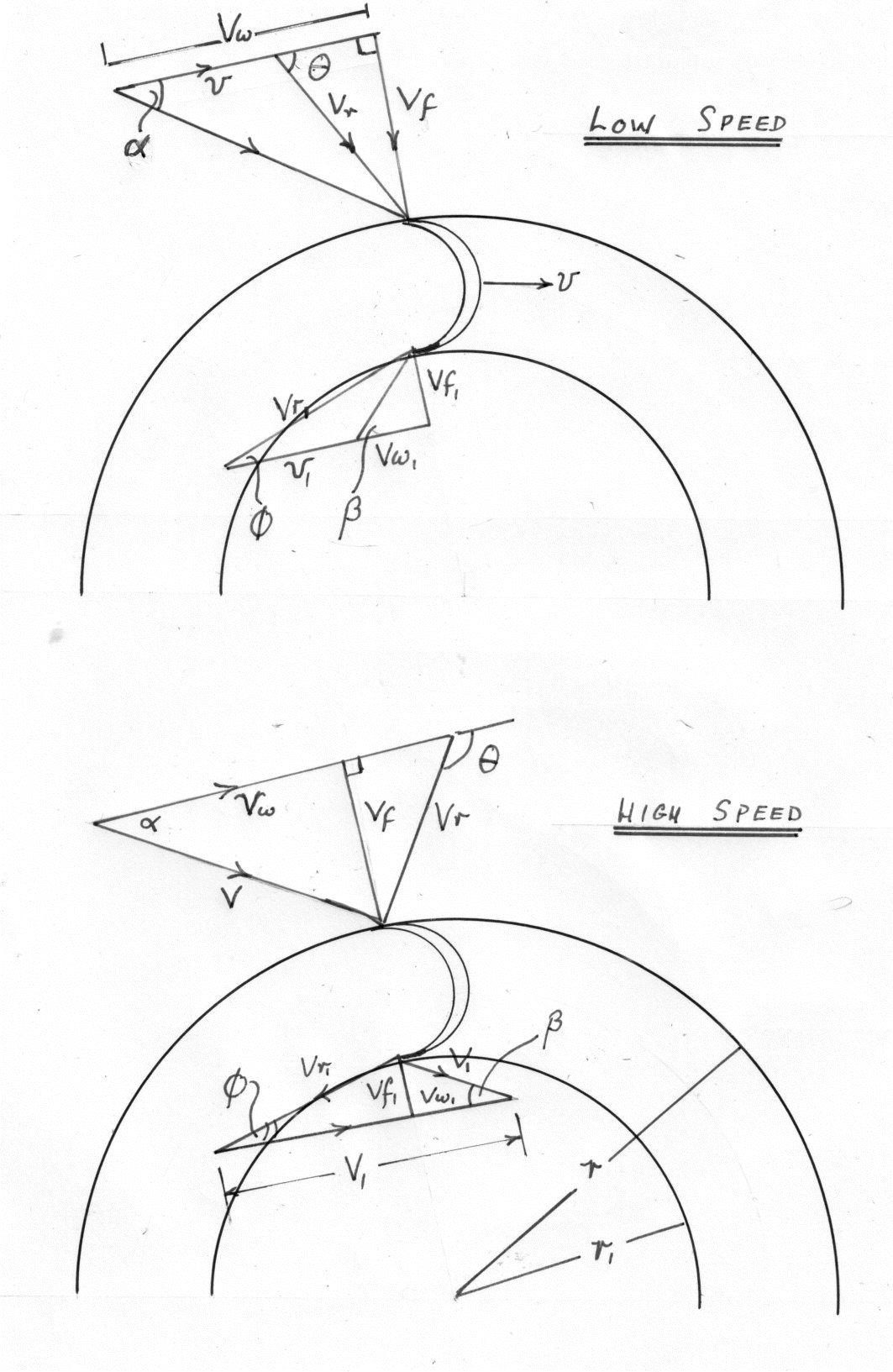
Let the weight of water/second striking the vanes be W lb/sec.
Tangential momentum/second at entry
Moment of momentum at entry =
Moment of momentum at outlet =
Torque on the vanes equals the change of moment of momentum per second
The work done per second on the vanes equals the Torque times the angular velocity
This is the EULER equation which can be applied to any type of turbine or centrifugal pumps
Efficiency of Turbines
1) Impulse Turbines ( No allowance for frictional losses)
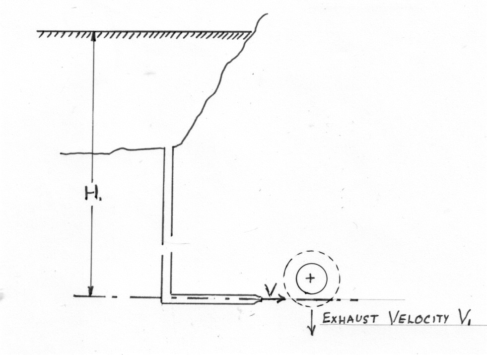
H is the total head behind the nozzle i.e. the sum of the pressure and velocity heads
V = Jet Velocity
= the exhaust velocity of water leaving the vanes.
Work done per second on the vanes ( per lb of water per second)
The theoretical hydraulic efficiency of the Turbine is equal to:-
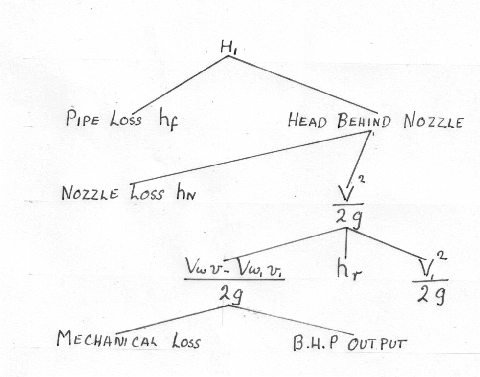
Impulse Turbine allowing for friction
The friction losses are in the nozzle () runner losand mechanical losses(
)
The effect of friction is to reduce V and i.e. to reduve the hydraulic η
The Actual Hydraulic Efficiency of the Turbine
The latter is based upon value obtained from the velocity triangles and momentum considerations and will thus take into account the various changes in velocity due to friction.
The Actual(overall efficiency) is based on the useful work out divided by the water power input. It therefore makes allowance for the frictional losses.
Example 1
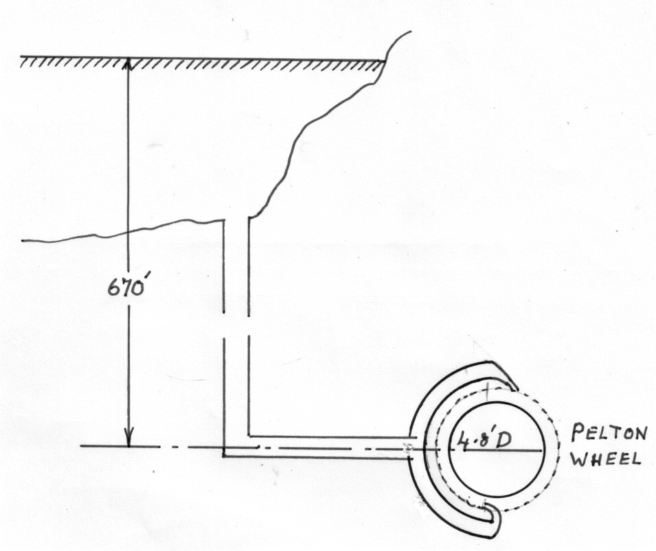
A Pelton wheel is driven by two similar jets, transmits 5000 Horse Power to the shaft running at 375 r.p.m. The head from the reservoir level is 670 ft. and the efficiency of power transmission through the pipeline and nozzles is 90% The centre lines of the jets are tangential to a 4.8 ft. diameter circle. The relative velocity decreases by 10% as the water traverses the bucket surfaces which are so shaped that they would, if stationary deflect the water through an angle of 165 degrees.
( one Horse Power (HP) is 550 ft.lb/sec. One cubic ft. of water weighs 62.4 lb. g = 32.2 ft/second squared)
Neglecting windage losses find:- 1. The efficiency of the runner
2. The diameter of each jet.
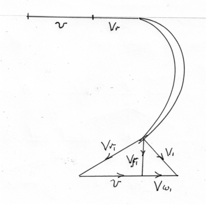
Velocity head of jet = 0.9 X gross head
Hence the hydraulic efficiency of the runner:-
If there are no mechanical losses
Whence W = 4890 lb/sec.
Therefore the nozzle diameter is 0.503 ft. 0r approx.6 inches
Reaction Turbines
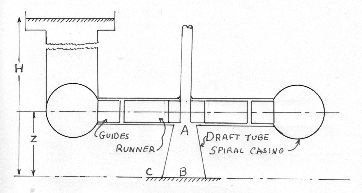
Inward radial flow; mixed flow; or axial with a propeller shaft. They may be sited below the tail race or above it with a draft tube.
V = The absolute velocity at the entry tot he runner
= The absolute velocity at the exit of the runner
h is the head.
1. LOW SUPPLY HEAD. Usually an open flume supply with a short Pinstock. e.g. Propeller Turbine. H is the vertical height from the water level in the fore- bay to the level in the Tail Race
2. LARGER HEADS. Long Pinstock and smaller water through put e.g. Radial floe Francis Turbine. H is now the total head (i.e. Pressure; velocity; and Datum) in the supply pipe just before entering the Turbine casing and is relative to the tail stock Datum.
The Gross Head in this case s measured from the supply reservoir and includes Pinstock losses.
DRAFT TUBE. This is designed to convert Kinetic Energy of discharge into Pressure. This gives extra suction through the Turbine. i.e. It enables the height Z ( see diag) to be included into the Supply head H.
Apply Bernoulli at A and C (see diag)
In practice the height Z is limited to avoid cavitation at A
If there are no losses in the runner; the supply system or draft tube.
Then the work done by the water on the runner (W.D.)
(if there is no Draft tube or if it is parallel)
The Theoretical Hydraulic Efficiency η
NOTES
1. For a Reaction Turbine
2. For Axial Flow
For radial flow
3. Velocity of Flow
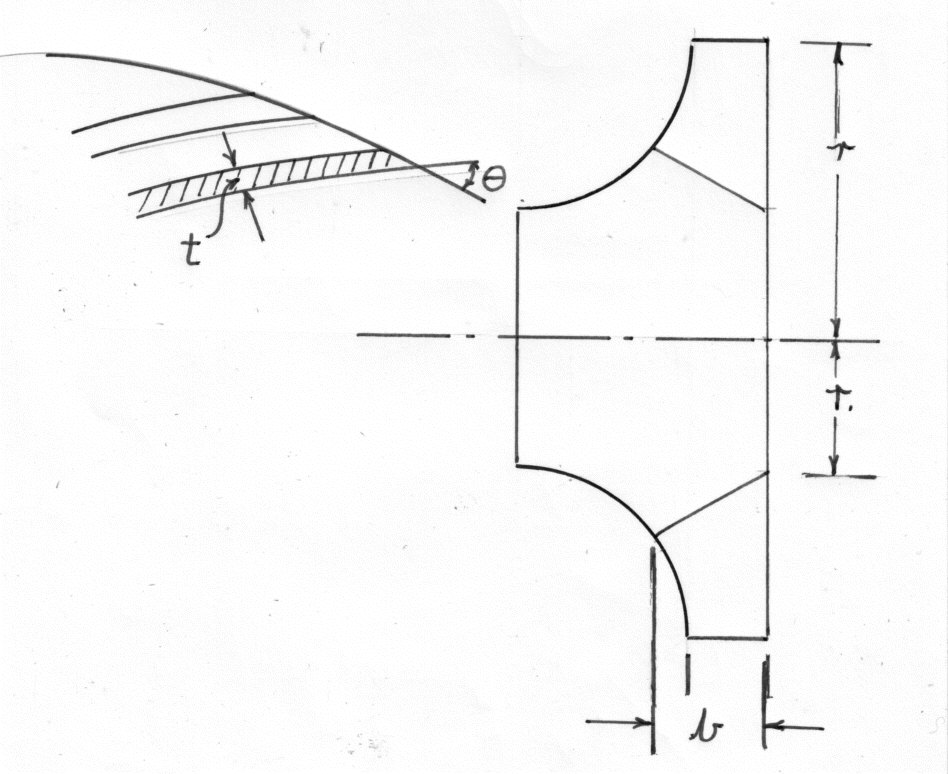
{NB. Reaction Turbines run full}
Let "s" be the number of blades; "T" the blade thickness and "b" the width of the runner.
the circumferential area of flow at inlet
Where k is the blade factor
Therefore the rate of flow through the Turbine "Q"
Similarly at the outlet
Unless otherwise stated it is normal to take
4. Variations of pressure head across the Turbine passage. Assuming no losses
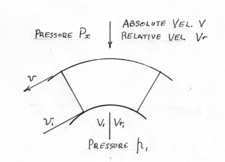
Applying Bernoulli to the absolute flow
Example 2
In a Francis type Turbine, the guide-vane angle is 8 degrees, the inlet angle of the moving vanes is 110 degrees and the outlet angle is 20 degrees ( see diagram). Both the fixes and moving vanes reduce the flow by 15%.
The runner is 24 inches outside diameter and 16 inches inside diameter and the widths at the entrance and exit are 2 and 3 inches respectively.
The pressure at entry to the guides is + 87 ft.head and the kinetic energy there can be neglected. The pressure at discharge is - 6 ft.head.
If the losses in the guides and moving vanes are taken as where f is the radial component of flow calculate:-
a)The speed of the runner in r.p.m. for tangential flow on to the running vanes
b) The horse-power given to the runner by the water.
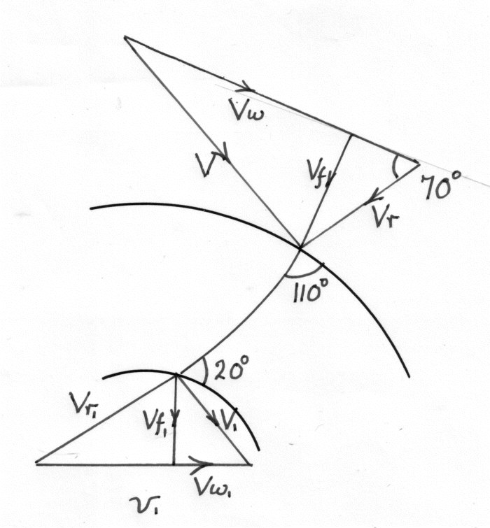
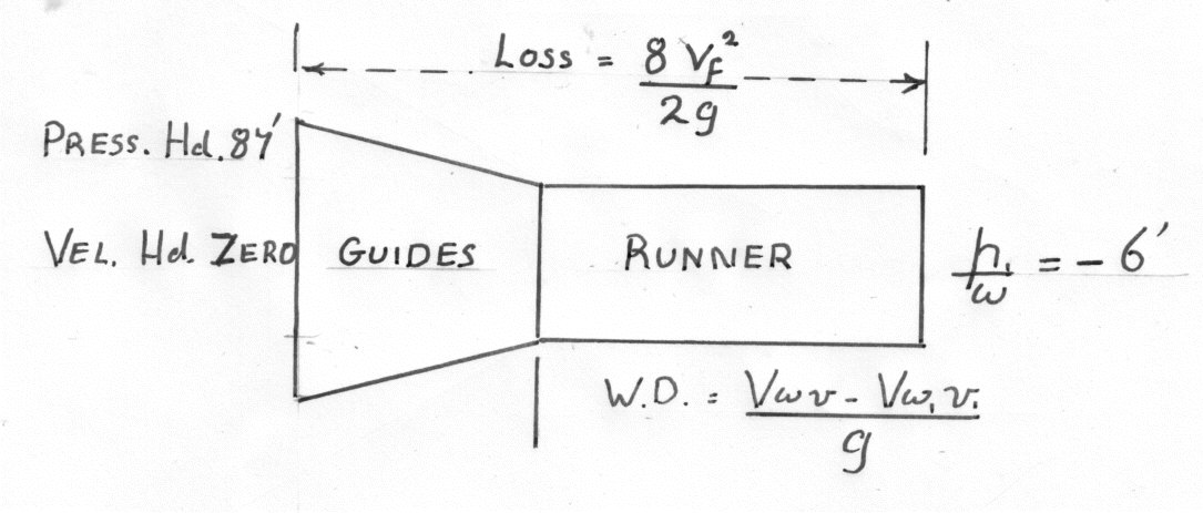
To find speed and horse-power.
Applying Bernoulli at the inlet to the guide vanes and the outlet of the runner.
From the velocity triangles ( above)
Weight of water per second
Work Done per Lb. of water is given by:-
PRINCIPLES OF SIMILARITY WHEN APPLIED TO TURBINES.
( The figures used in this section are based on the ft.; slug ; Second . system)
1) Specific speed of a turbine
This is the speed (r.p.m.)at which a similar model of the Turbine would run under a head of 1ft. when of such a size as to develop 1 H.P. The suffix "s" is used to denote the values associated with the Specific Turbine)
Each type of Turbine ( Pelton Wheel; Francis etc.) has it's own characteristic limits
of.
A similar model means :-
a) Geometrically similar - made from the same drawings but to a different scale.
b) Dynamically similar - Operating conditions and equal efficiencies.
Thus in comparing two similar turbines all the linear dimensions will be in the same ratio; All angles will be the same; the velocity triangles will be geometrically similar and all velocities will be in the same ratio.
But Q = The Area of flow X the Velocity of flow
But the weight of water per second ;W
Thus the H.P.output of the Turbine P ( The efficiencies are equal)
But for the specific Turbine
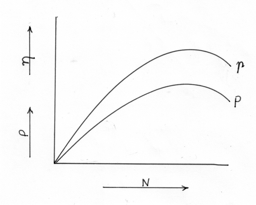
NOTES ON SPECIFIC SPEED.
a) is based on the values of N; P; and H used at the design point. i.e. At
maximum efficiency.
b) is NOT dimensionless and there are different values in each of the
measurement systems.
Unless otherwise stated, N is in r.p.m.
P is in Brake Horse Power(b.h.p.)(
c) can be made dimensionless and still be a constant by dividing by
and this is called the " SPEED NUMBER"
d) For a particular type of Turbine is constant.
e) for different types of Turbine and a comparison of heads for a
particular power and speed.
1. For a Pelton Wheel Head required 520 ft.
2. For a Turgot Turbine Head required 335 to 180ft
3. For a Francis Turbine Head required 180 to 40ft
4. For a Propeller Turbine Head required 40 to 23ft
NB. The above head requirements are for a turbine to develop 100 b.h.p. at 1000r.p.m.
f) An example of the use of Specific Speed
What turbine would be used if there was a supply of 10 cu.ft/sec under a head of 225 ft. ? Assume an efficiency of 80%.
Power Output = Water h.p.input X Efficiency
It would therefore be necessary to use a Turgot Turbine. However it might be possible to use a Pelton Wheel with two jets.
Try a Pelton Wheel with four Jets
This would be a practical proposition but would result in some loss of efficiency due to interference between the jets. A better alternative would be to have two wheels on the same shaft with two jets per wheel.
2. UNIT CONDITIONS
Unit operating conditions for a turbine are those under which that particular turbine would run when working under a head of one ft. ( or unit head in any other system) assuming there to be change in efficiency.
This allows the performance of a given turbine to be compared when working under different heads and enables the characteristic curves to be drawn which show the efficiency at all running conditions.
a) Unit Speed
If N is the speed under a head H
b) Unit quantity of a Turbine is the flow through the turbine when operating under a head of one ft. assuming similar conditions.
If Q = the flow under a head H
Q = area of flow X velocity
And since the area is constant and the velocity is
c) Unit Power of a given turbine is the power output of the turbine when operating under a head of one ft. assuming no change in efficiency .
If P is the output under a head H