
Centrifugal Pumps
Velocity triangles, Manometric Head and Efficiency
You're viewing an older version of this page (#3784). View the current version.
Introduction
These can be regarded as the inverse of a reaction turbine in that they convert mechanical energy into a head of liquid. The flow is always outwards (Except for propeller pumps) and the pump must run full. This means that before use they need to be filled with liquid ("primed"). The suction lift is limited to avoid cavitation.
The centrifugal pump is inherently less efficient than a turbine because of smaller losses when converting pressure energy to kinetic energy than visa versa.
The rotating impeller creates a forced vortex in the passages of the pump and the efficiency depends largely upon the extent to which the high velocity head is converted to pressure head.
Please Note that this page has been edited and extra worked examples added. The new page is shown under the heading"Single Stage Centrifugal Pumps"
Recuperators
Vortex Chamber
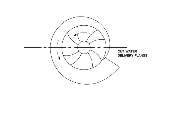
The gradual increase of area decreases the velocity of flow and increases the pressure. The losses are high due to eddy currents caused by the radial component of flow from the impeller. There is also an out of balance radial thrust.
Parallel Vortex Chamber
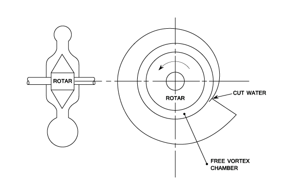
A free spiral vortex is formed in the parallel vortex chamber. which helps to steady the flow before discharging into the spiral vortex.
Diffuser also known as a turbine pump
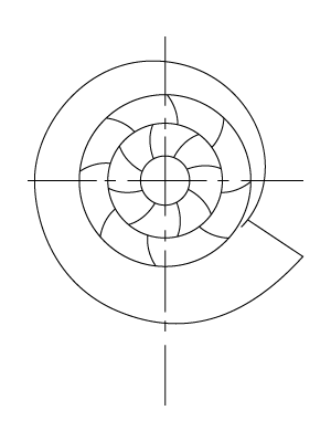
This diffuser consists of a fixed ring of guide vanes surrounding the impeller. The pump's velocity energy is converted into pressure energy in the diffuser which discharges into the volute.
The inlet angle of the guide vanes equals the outlet absolute velocity angle of the impeller.
Velocity triangles
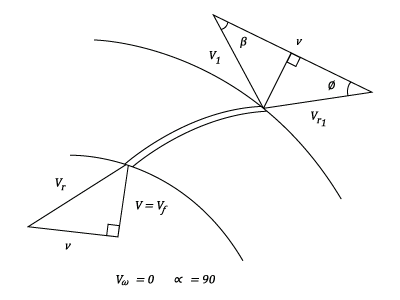
These are similar to those produced for turbines but the flow is now outwards.
- It is usual to assume that water enters the impeller radially. i.e. without whirl. Thus
the diffuser vane angle. (if any)
and
- The Euler Equation: The work done by the vanes on the water
- Variation of pressure across the impeller.
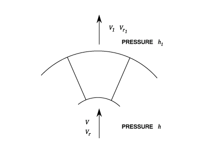
Work done theory
The total energy at outlet = Total energy at input + Work done - Losses or
Vortex theory
Difference in pressure head = centrifugal head + difference in velocity head - losses
The Efficiency of Centrifugal Pumps
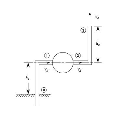
Apply Bernoulli's equation at (0) and (1) Therefore the reading of the pressure gauge at the suction flange is:
Apply Bernoulli's equation at (2) and (3)
Therefore the pressure gauge reading at the delivery flange is:
Thus the reading of the pressure gauge across the pump flanges equals:
= (Actual lift) +(Friction head lost in pipe) + (Difference of velocity head across pump) + (the velocity head at discharge)
Manometric Head
This is defined by British Standards as the sum of the actual lift + the friction losses in the pipes + the discharge velocity head. However for special pumps allowance must also be made for the velocity of flow towards the suction intake and any pressure differences at the water surfaces in the supply and receiving tanks.
Thus:
Commonly the suction and delivery pipes are of equal diameter. In which case:
If the two pressures are registered on different gauges. A correction must be made for any difference in the datum heights of the gauges.
Manometric efficiency
This is defined as the Manometric head divided by the work done by the impeller on the water. and
is usually zero.
The Total Work Done by the Pump
This differs by from the Euler head input by
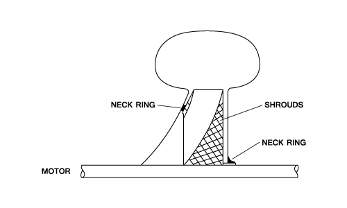
- The mechanical losses in the bearings.
- Disc friction on the outside of the impeller shroud.
- Leakage losses in pumping water that leaks through the neck rings to waste or back into the suction side.
Actual Efficiency
The actual efficiency is obtained by dividing the water power output by the driving motor power input
It can be shown that the Gross Lift (Manometric Head) , where
=Speed,
=Delivery and
,
,
are Constants.
Example 1 [imperial]
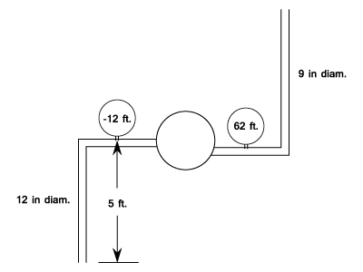
A centrifugal Pump impeller has an external diameter of 12 inches and a discharge area of 1.2ft. The blades are bent backwards so that the direction of the relative velocity at the discharge surface makes an angle of 145 degrees with the tangent to this surface drawn in the direction of the impeller rotation. The diameters of the suction and delivery pipes are 12in. and 9in. respectively.
Gauges at points on the suction and delivery pipes close to the pump and each 5ft. above the level of the supply sump show heads of 12 ft. below and 62ft. above atmospheric pressure when the pump is delivering 7.2 cusec. of water at 1200r.p.m. It requires 96 h.p. to drive the pump.
Find
- a) The overall efficiency.
- b) The manometric or hydraulic efficiency assuming that the water enters the impeller without shock or whirl.
- c) The loss of head in the suction pipe.
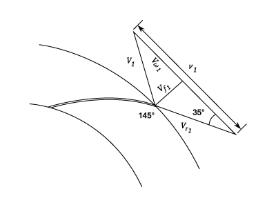
- a) Overall efficiency
Suction Pipe Velocity
Delivery Pipe Velocity
Manometric Head
Pump output
Thus the overall
- b) The Manometric efficiency equals the Manometric head divided by the Euler Head
The velocity of flow =
From Velocity triangle
Work done per lb. of water The Manometric
- c) The Head Lost in the Suction Pipe
Apply Bernoulli'\b{s equation} to the supply sump and at the suction flange:
- The overall efficiency is
- The manometric efficiency is
- The loss of head in the suction pipe is
Example 2 [imperial]
A Centrifugal Pump has vanes curved backwards so that the tangent to the vanes makes an angle of 30 degrees with the tangent to the periphery. The impeller diameter is 10 in. and the width 3/4 in. Vane thickness takes up 15% of the peripheral area.
Assuming that 50% of the kinetic energy at exit from the impeller is lost in eddies, calculate, on the usual assumptions, what will be the lift and manometric efficiency when discharging 400 gallons/min. at a speed of 1100r.p.m.
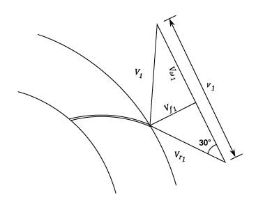
Thus:
And:
Therefore work done per second is
(Assuming
)
The Casing losses
Therefore, neglecting the impeller loss: and the manometric
- The lift is
- The manometric efficiency is