Moments of Inertia
Describes the determinqtion of Moments of Inertia by both analylitical and graphical methods
You're viewing an older version of this page (#3420). View the current version.
Moments of inertia
The moment of Inertia "I" which is also called the second moment of area is defined as either depending upon which axis the moment is taken. It can be shown that the sum of
equals J ( The polar Moment of Inertia). This relationship is called the " perpendicular axis theorum" which states that the sum of the moments of area about any two axis in the plane is equal to the moment of inertia about the axis perpendicular to the plane, the three axis being concurrent.
It follows that the sum of the moments of inertia about any two perpendicular axes through a given point in the plane is constant.
Circular Section
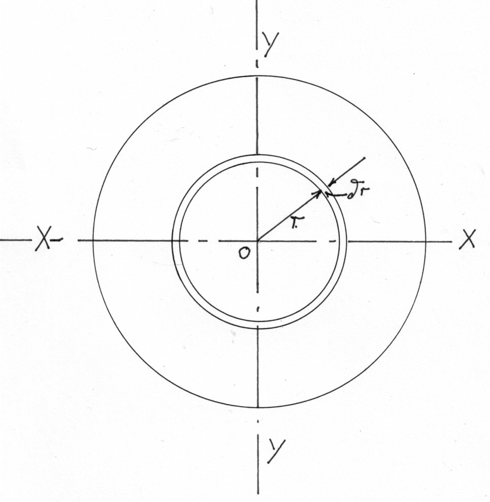
To calculate the polar moment of inertia J about the centre of the section O
but and by the parallel axis theory ( For proof of theorem see next section) and since
being moments of inertia about a diameter.
for a hollow section with external diameters and internal diameters of D and d
Section Modulus Z and Moment of resistance.
The ratio I/y max is called the section modulus Z, so that the maximum stress equals M/Z. The bending moment which can be carried by a given section for a limiting stress ic called the Moment of resistance
The parallel axis theorem
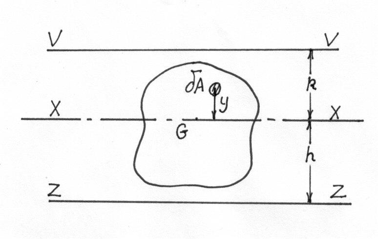
by definition
Stated in words: The moment of inertia about any axis is equal to the moment of inertia about a parallel axis through the centroid plus the area times the square of the distance between the axes.
It should be noticed that the moment of inertia through the centroid is the minimum value for any axis in that particular direction.
If it is required to transfer from one axis zz to a parallel axis VV, neither being through the centroid, then the operation must be done in two stages.
Calculations of moments of inertia
a) rectangular section.
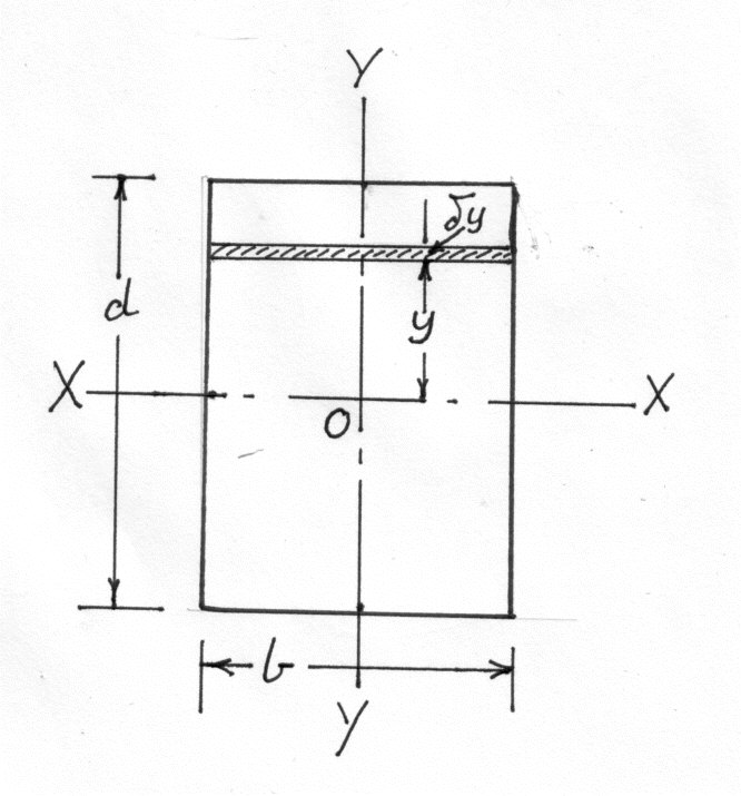
From the diagram
For a hollow section of outside dimensions B:D: and inside dimensions b;d;
b) "I" section
In the case of standard sections the moments of inertia are computed graphically from the actual shape of the cross section as rolled. However a reasonable approximation can be made by estimating the mean flange thickness and working from a series of rectangles.
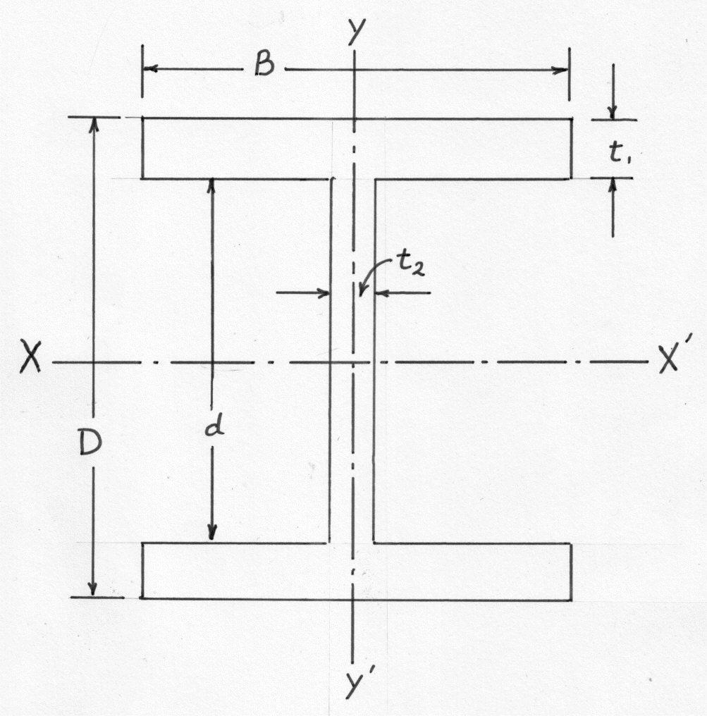
Using the dimensions shown, the moment of inertia about XX may be obtained by
subtracting that for rectangles wide and d deep from the overall
figure for B ties D.
Alternatively, for greater accuracy of calculation, the web and flanges may be treated separately using the parallel axis theorem for the flanges.
Where is the distance between the centroid axis of the flange itself and the principle axis of the whole cross section XX. The term
is very small and can usually be neglected
the width being the dimension parallel to YY and the depth parallel to XX
The Graphical determination of Moment of Inertia.
Assume that it is required to find the Moment of Inertia of an irregular shape about its centroid, XX.
Let ZZ be a convenient axis Outside the section. Note ZZ is parallel to XX.
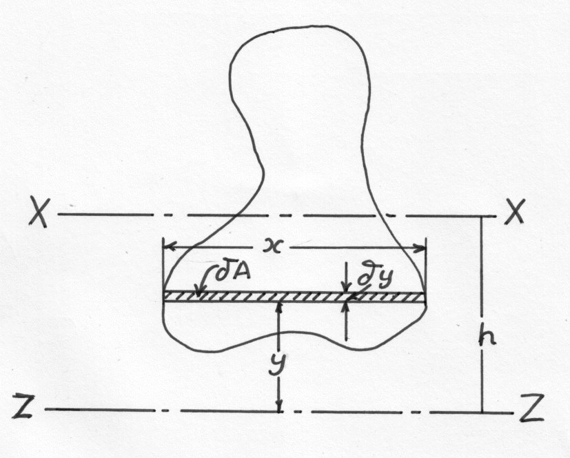
Divide the Shape up into strips of area which are parallel to ZZ and at a distance y from it. As each strip is of the same width,
, The areas
will be proportional to their width x.
It is now possible to complete the following table:-
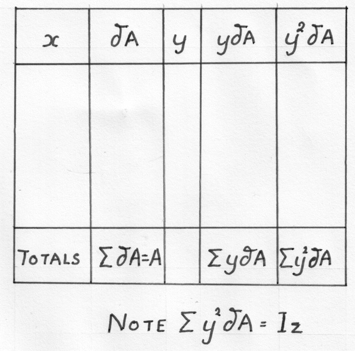
If h is the distance from the centroid then taking Moments about ZZ
Using the Parallel Axis Formula (Equation 9)
Appendix
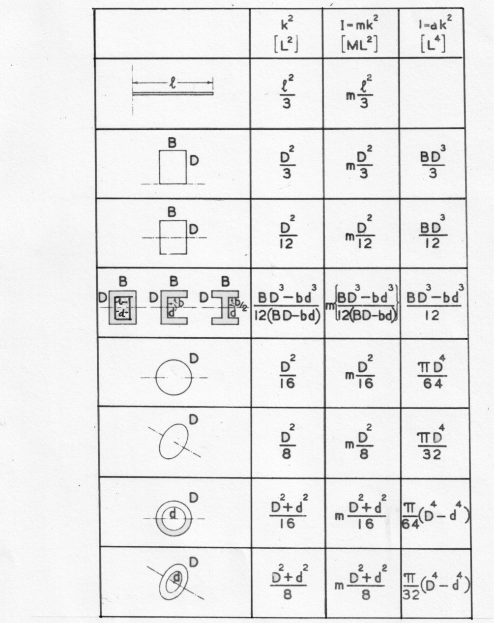
The following table shows Moments of Inertia for commonly occurring geometric shapes. For Rolled Steel Joists; Hollow sections; and other structural shapes it is more accurate to use tables produced by the manufactures of these products.