
Moments of Inertia
Worked examples involving Bending Stess and Moments of Inertia
You're viewing an older version of this page (#3419). View the current version.
Please Note: Reference pages on the bending moments of beams is in preparation and will be published shortly. In the mean time the formulae for the following examples are quoted without proof.
The General Equation for bending is used throughout. The proof of this is to be found in "Engineering/Materials/Bending Stress". For convenience the equation is written here and is as follows:
Where f is the stress at a distance y from the Neutral Axis
- M is the Bending Moment
- I is the Moment of Inertia of the section
- E is Young's Modulus
- R is the Radius of curvature
It is obviously important to use the same units throughout!
Example 1
The beam of a symmetrical I section is simply supported over a span of 30 ft. If the maximum permissible stress is 5 tons/sq.in., what concentrated load can be carried at a distance of 10 ft from one support?
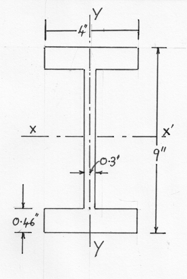
Whilst it is not stated in the question, it is normal practice to load an I-section with XX as the axis of bending. Thus the Bending Moment is in the YY plane.
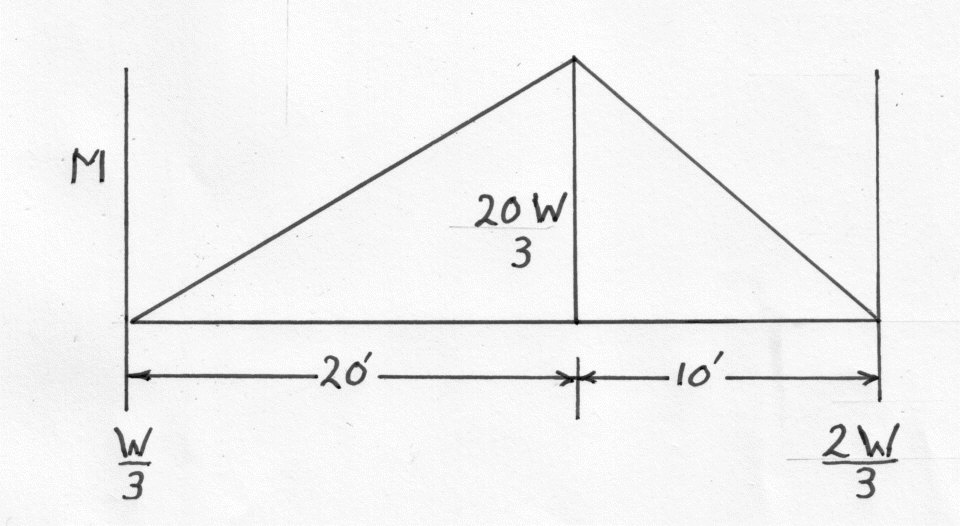
If the load is W tons then the maximum Bending Moment is given by:-
i.e.
Using the method for establishing the Moment of Area of an I-section beam shown in "Engineering/Materials/Bending"
Using the General equation of Bending
Example 2
An "I" section beam has a depth of 14 ins. and is freely supported at its ends. The Moment of Inertia is . Over what span can a uniform load of 1 ton/ft. be carried if the maximum stress is 4 tons/sq.in. What additional central load can be carried if the maximum stress is 4 tons/sq.in.
Bending Moment = where w = weight per unit length
As this is a uniform I section the neutral axis will pass through the geometric centre. Applying the formula for bending of beams
If a central load of W is now placed on the beam, this will increase the bending moment by:
And the B.M. due to a distributed load is
Thus the Total Bending Moment in the centre of the span is now
The General Equation of Bending
Example 3
The cross-section of a cast iron beam is shown in the diagram. The loading is in the plane of the web and the upper portion of the section is in compression. If the maximum permissible stresses are 2 tons/sq in in tension and 3 tons/sq.in. in compression find the moment of resistance of the section and the actual maximum stress.
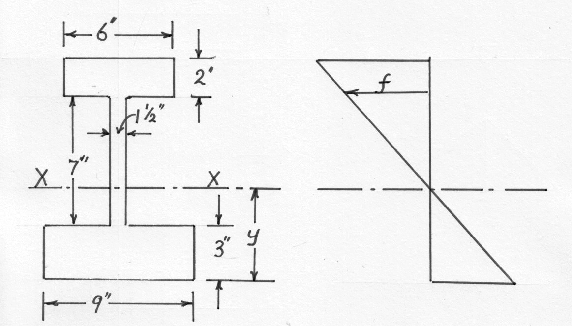
Since the neutral axis XX passes through the centroid it is necessary to first find its position. This and the position of the total moment of inertia about XX can be most conveniently found by tabulating as follows:
- y is the distance of the centroid of each area from the bottom of the section.
is the moment of inertia of each area about its own centroid axis parallel to XX
- h is the distance between each centroid axis and XX.
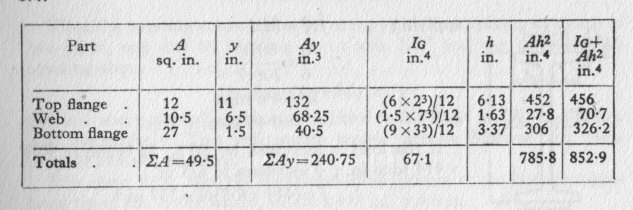
By Moments
For the whole section about the Neutral Axis .
The maximum distances from the Neutral axis are 4.87 in. on the tension side and 7.13 in. on the compressive side.
Using the General Equation of Bending
For Tension
For Compression
The limiting value is therefore 351 yon-in which corresponds to the maximum tensile stress of 2 tons/sq.in and a maximum compressive stress of:-
Alternatively it may be argued that the actual maximum stress ratio must be determined by the distances from the neutral axis i.e. from which it can be deduced that the tensile stress is the limiting one, as the maximum compressive stress is less than the permissible value. The moment of resistance is then calculated on the basis of 2 tons/sq.in tensile stress
Note: Unsymmetrical sections are used for Cast Iron Beams because the material is stronger in compression than tension. Clearly the beam must be used with the larger flange on the tension side.
Example 4
A 12 in. by 5 in. Steel Beam is to be used as a Cantilever 10 ft. long. If the permissible stress is 8 tons/sq.in. , what uniformly distributed load can be carried?
If the Cantilever is to be strengthened by steel plates 1/2 inch thick welded to the top and bottom flanges, find the width of the plates required to withstand an increase of 50% in the load. Calculate as well the length over which the plates should extend for the maximum stress to remain the same.
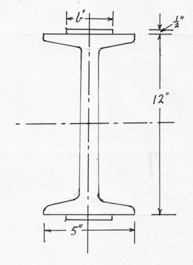
From standard tables for beams
If W is the total load in Tons and the length of the beam is measured in inches then:
Using the General Equation of Bending
We have been given a maximum permissible stress of 8 tons/sq.in. and the distance y as 6 ins.
and
This is equivalent to 0.6 tons per foot run of beam. If the load is to be increased by 50% and 0.5 in. plates are welded onto both flanges then
becomes
and
.
The increase in the moment of inertia is . This is the Moment of Inertia of the two flange plates about XX. If their width is b then
The length over which the plates must be extended is determined by the position at which the maximum stress, under the increased load, in the beam itself is equal to 8 tons/sq.in.
If x is the distance from the free end where this occurs then:
Substituting in the Bending Stress equation (14)
Hence
The Maximum Bending Moment occurs at the fixed end and the welded plates should extend for :
Example 5
The I beam shown in the diagram is simply supported at its ends over a 20 ft. span and carries a central load of 5 tons which acts through the Centroid,. The line of action is as shown. Calculate the maximum stress.
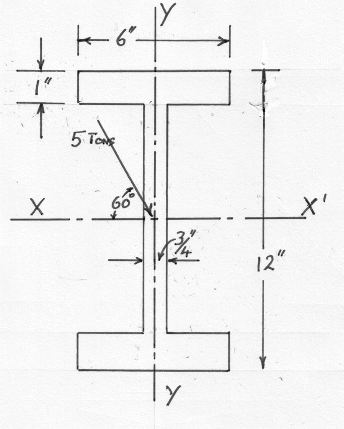
The section being symmetrical, the Centroid is at the centre of the web and the principle axes are XX' and YY.
For the flange:
For the web:
Combined
The Maximum bending moment is
This must be resolved into in the plane YY' and
in the plane XX
Then the Bending Stress at any point (x,y) in the section is made up of two parts, one due to bending about the XX' axis and the other due to bending about the YY' axis.
i.e.
where x and y are reckoned to be positive to the right of YY' and below XX', respectively. This will ensure tensile stress is positive and compressive stress negative.
By inspection it can be seen that the maximum stress occurs at the bottom right-hand tip of the lower flange where and
.
Hence
Example 6
A Cantilever has a free length of 8 ft. It is of "T" section with a flange of 4 ins. by 3/4 ins. and a web of 8 ins. by 1/2 ins.. The flange is in tension. What load per foot run can be applied if the maximum tensile stress is 2 tons/sq.in. What is the compressive stress produced by this loading.
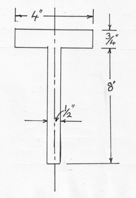
The maximum Bending moment for a cantilever is given by:
where w is the weight of the cantilever in tons/inch.
The moment of Inertia for a rectangular section is given by:-
Thus
And
To find the centroid the easiest way to do this is to draw up the following table:
TODO: Table
The distance of the Centroid from XX' is
and
Applying the General Equation of Bending
or
On the compressive side at the bottom of the "T"
Applying the General Equation of Bending
therefore the maximum compressive stress is .