
Describes the Macaulay Method for calculating the deflection of Beams

You're viewing an older version of this page (#3447). View the current version.

View versions (4)

Macaulay's Method

Using the Calculus to find expressions for the deflection of loaded beams (See Deflection of Beams Part 1) It is normally necessary to have a separate expression for the Bending Moment for each section of the beam between adjacent concentrated loads or reactions. Each section will will produce its own equation with its own constants of integration. It will be appreciated that in all but the simplest cases the work involved will be laborious, the separate equations being linked together by equating slopes and deflections given by the expressions on either side of each "junction point. However a method devised by Macaulay enables one continuous expression for bending moment to be obtained and provided that certain rules are followed the constants of integration will be the same for all sections of the beam.

It is advisable to deal with each different type of load separately.

Concentrated Loads

Measuring x from one end write down an expression for the Bending Moment in the last section of the beam enclosing all less than x in square brackets, i.e.
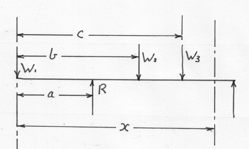
E\,I\,\frac{d^2y}{dx^2}\;=\;M\;=\;-\,W_1x\;+\;R[x\;-\;a]\;-\;W_2[x\;-\;b]\;-\;W_3[x\;-\;c]
(1)
13108/img_mac_1.jpg

Subject to the condition that all terms for which the quantities in the square brackets are negative, are omitted ( i.e. given a value of zero), this equation may be said to represent the bending moment for all values of x. If x is less than b then both the last two terms are omitted and so on.

The brackets are integrated as a whole. i.e.

E\,I\,\frac{dy}{dx}\;=\;-\,W_1\frac{x^2}{2}\;+\;\frac{R}{2}[x\;-\;a]^2\;-\;\frac{W_2}{2}[x\;-\;b]^2\;-\;\frac{W_3}{2}[x\;-\;c]^2\;+\;A
(2)
And\;\;\;\;E\,I\,y\;=\;-\,W_1\frac{x^3}{6}\;+\;\frac{R}{6}[x\;-\;a]^3\;-\;\frac{W_2}{6}[x\;-\;b]^3\;-\;\frac{W_3}{6}[x\;-\;c]^3\;+Ax\;+\;B
(3)

By doing so it can be shown that the constants of integration are common to all sections of the beam, e.g. if \displaystyle x\;=\;b\;-\;\Delta

E\,I\;\frac{dy}{dx}\;=\;-\left(\frac{W_1}{2} \right)(b\;-\;\Delta )^2\;+\;\left(\frac{R}{2} \right)(b\;-\;\Delta \;-\;a)^2\;+\;A
(4)
And\;\;\;\;\;\;E\,I\;y\;=\;-\left(\frac{W_1}{6} \right)(b\;-\;\Delta )^3\;+\;\left(\frac{R}{6} \right)(b\;-\;\Delta \;-\;a)^3\;+\;A(b\;-\;\Delta )\;+\;B
(5)
Blank
E\,I\;\frac{dy}{dx}\;=\;-\left(\frac{W_1}{2} \right)(b\;+\;\Delta )^2\;+\;\left(\frac{R}{2} \right)(b\;+\;\Delta \;-\;a)^2\;-\left(\frac{W_2}{2} \right)\Delta ^2+\;A'
(6)
And\;\;\;\;\;\;E\,I\;y\;=\;-\left(\frac{W_1}{6} \right)(b\;-\;\Delta )^3\;+\;\left(\frac{R}{6} \right)(b\;+\;\Delta \;-\;a)^3\;-\left(\frac{W_2}{6} \right)\Delta ^3+\;A'(b\;+\;\Delta )\;+\;B'
(7)

Now as \displaystyle \Delta \rightarrow 0 the slope and deflection values must correspond (i.e.) at x = b from which it can be seen that A = A' and B = B'. The values of A and |B are found as before ( Part 1)

Uniformly Distributed Loads.

Supposing that a uniformly distributed load is applied from a distance a to a distance b measured from one end. (A). Then in order to obtain an expression for the Bending Moment at a distance x from the end, which will apply for all values of x, it is necessary to continue the loading up to the section at x compensating this with an equal negative load from b to x (See diagram)
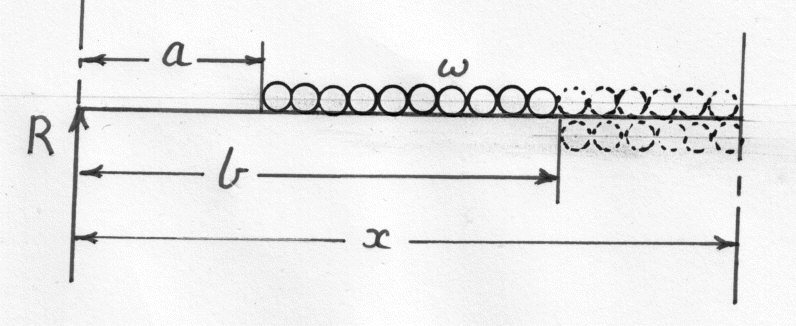
Hence\;\;\;\;\;M\;=\;Rx\;-\;\frac{w}{2}[x\;-\;a]^2\;+\;\frac{w}{2}[x\;-\;b]^2
(8)
Blank
13108/img_mac_2.jpg

Each length of the loading acts at its centre of gravity. The square brackets are interpreted as before.

For x>a but<b, omit [x - b] and:-

Hence\;\;\;\;\;M\;=\;Rx\;-\;\frac{w}{2}(x\;-\;a)^2
(9)

This is clearly correct. The remaining steps of integration are the evaluation of the Constants now proceeds as before.

Concentrated Bending Moment
13108/img_mac_6_1.jpg

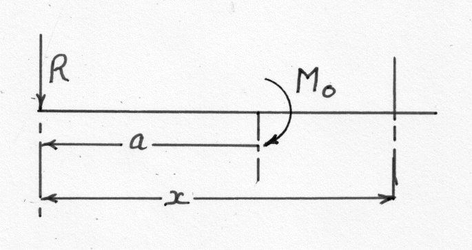
It is possible to write:-

E\,I\,\frac{d^2y}{dx^2}\;=\;M\;=\;-\,Rx\;+\;M_0[x\;-\;a]^0
(10)
E\,I\,\frac{dy}{dx}\;=\;-\,R\frac{x^2}{2}\;+\;M_0[x\;-\;a]\;+\;A\;\;\;\;\;\;etc.
(11)

Example 1

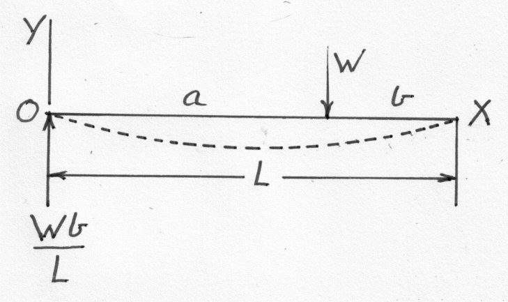
A simply supported beam of length L carries a load W at a distance a from one end and b from the ( a > b). Find the position and magnitude of the maximum deflection and show that the position is always approximately within L/13 of the centre. (U.L.)
13108/img_mac_7.jpg

The maximum deflection (i.e.) zero slope will occur on the length a since a>b

Taking the axes as shown in the diagram.

E\,I\,\frac{d^2y}{dx^2}\;=\;M\;=\;\left(\frac{Wb}{L} \right)\,x\;-\;W[x\;-\;a]
(12)

Integrating

E\,I\,\frac{dy}{dx}\;=\;\left(\frac{Wb}{L} \right)\left( \frac{x^2}{2}\right)\;-\;\left(\frac{W}{2} \right)[x\;-\;a]^2\;+\;A
(13)

And Integrating again gives:-

E\,I\,y\;=\;\left(\frac{Wb}{L} \right)\left( \frac{x^3}{6}\right)\;-\;\left(\frac{W}{6} \right)[x\;-\;a]^3\;+\;Ax\;+\;B
(14)

At x = 0 y = 0 and therefore B = 0

At x = 0 y = L

\therefore\;\;\;\;\;A\,L\;=\;-\;\left(\frac{Wb}{L} \right)\left(\frac{L^3}{6} \right)\;+\;\left(\frac{W}{6} \right)b^3
(15)

From which:-

A\;=\;-\;\left(\frac{Wb}{6L} \right)\left(L^2\;-\;b^2 \right)
(16)

We need to find the value of x when \displaystyle \frac{dy}{dx} is zero. Using equation (13) and omitting [x - a} ( We can do this because at zero slope x < a when a > b )

\therefore\;\;\;\;\;\;\left(\frac{W\,b}{L} \right)\left(\frac{x^2}{2} \right)\;-\left(\frac{W\,b}{6L} \right)(L^2\;-\;b^2)\;=\;0
(17)
Hence\;\;\;\;\;\;x\;=\;\sqrt{\left[\frac{L^2\;-\;b^2}{3} \right]}
(18)

At the point of maximum deflection. To find the value of this deflection substitute into equation (14)

E\,I\,y\;=\;\frac{W\,b}{L}\times \frac{(L^2\;-\;b^2)^\frac{3}{2}}{6\times3\;\sqrt{3}}\;-\;\frac{W\,b}{6L}\times\frac{(L^2\;-\;b^2)^\frac{3}{2}}{\sqrt{3}}
(19)
y\;=\;-\,\frac{W\,b}{L}\times \frac{(L^2\;-\;b^2)^\frac{3}{2}}{9\;\sqrt{3}\times E\,I\,L}
(20)

Re-writing Equation (17) to obtain the value of x when dy/dx = 0 gives:-

x\;=\;\sqrt{\left(\frac{L^2\;-\;b^2}{3} \right)}
(21)

This gives the distance from the centre of the beam to be :-

Distance\;from\;Centre\;=\;\sqrt{\left(\frac{L^2\;-\;b^2}{3} \right)}\;-\;\frac{L}{2}
(22)

Which has a maximum value of

\frac{L}{\sqrt{3}}\;-\;\frac{L}{2}\;\approx \frac{L}{13}
(23)

Example 2

A simply supported beam of 20 ft. span carries two concentrated loads of 4 tons at 8ft. and 10 tons at 12 ft. measured from one end. Calculate (a) The deflection under each load (b) the maximum deflection.
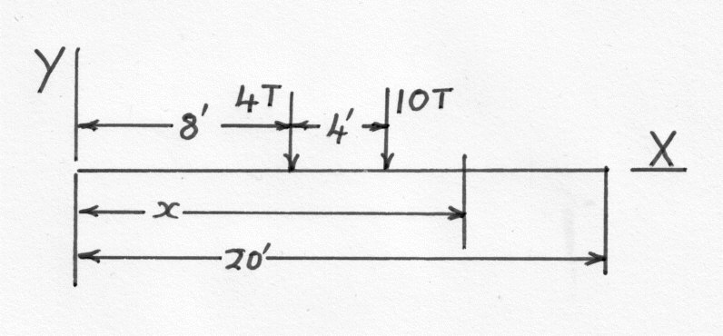
Tke\;E\;=\;13,200\; tons/in^2\;\;\;\;and\;\;\;\;I\;=\;1200\;in^4
(24)
Blank
13108/img_mac_8.jpg
Blank
Reaction\;at\;O\;=\;\frac{4\times 12\;+\;10\times 8}{20}\;=\;6.4\;tons
(25)
E\,I\,\frac{d^2y}{dx^2}\;=\;M\;=\;6.4\,x\;-\;4[x\;-\;9]\;-\;10[x\;-\;12]
(26)
Integrating\;\;\;\;\;E\,I\,\frac{dy}{dx}\;=\;3.2\,x^2\;-\;2[x\;-\;8]^2\;-\;5[x\;-\;12]^2\;+\;A
(27)
Integrating\;again\;\;\;\;\;E\,I\,y\;=\;\frac{3.2}{3}\,x^3\;-\;\frac{2}{3}[x\;-\;8]^3\;-\;\frac{5}{3}[x\;-\;12]^3\;+\;A\,x\;+\;B
(28)

When x = 0 y = 0 and therefore B = 0

When x = 20 y = 0

\therefore\;\;\;\;\;\;\;0=\;\frac{3.2}{3}\,20^3\;-\;\frac{2}{3}[20\;-\;8]^3\;-\;\frac{5}{3}[20\;-\;12]^3\;+\;20\,A
(29)

Giving A = -326.5 tons-ft.sq.

(a)

Under the 4 tons load x = 8 ft

\therefore\;\;\;\;\;\;\;E\,I\,y=\;\frac{3.2}{3}\,8^3\;-326.5\times 8\;=\;-\,2066\;tons-ft^3
(30)

Thus the deflection y is given by:-

y\;=\;-\;\frac{2066\times 12^3}{13200\times 1200}\;=\;0.225\,in.\;downwards
(31)

Under the 10 ton load x = 12 ft.

E\,I\,y\;=\;\left(\frac{3.2}{3} \right)\times 12\;-\;\frac{2}{3}\times 4^3\;-\;326.5\times12\;=\;-\,2118\;tons-ft.
(32)
\therefore\;\;\;\;\;y\;=\;\frac{2118\times12^3}{13200\times1200}\;=\;0.231\;in.\;downwards
(33)

Note. For those not used to the fps system the \displaystyle 12^3 is needed to convert from \displaystyle ft.^3\;\;\;to\;\;\;in.^3

(b) The maximum deflection can be judged to occur between the loads and we can therefore omit the term in [x - 12] as it will be negative. At the maximum deflection the slope of the beam will be zero and hence using equation (27) and the result from equation (29) we can write

3.2\,x^2\;-\;2(x\;-\;8)^2\;-\;326.5\;=\;0
(34)
\therefore\;\;\;\;\;1.2\,x^2\;=\;32\,x\;-\;454.5\;=\;0
(35)
Hence\;\;\;\;\;x\;=\;\frac{-32\;+\;\sqrt{32^2\;-\;4\times 1,2\times 454.5}}{2\times 1.2}\;=\;10.3\;ft.
(36)

Note. This comes between the 4 ton and 12 ton loads as assumed

Thus the maximum deflection is given by:-

\hat{y}\;=\;\frac{\left\{(3.2/3)\times 10.3^3\;-\;(2/3)\times6.3^3\;-\;326.5\times10.3^3  \right\}12^3}{13200\times 1200}\;=\[0.258\;in.
(37)

Example 3

3

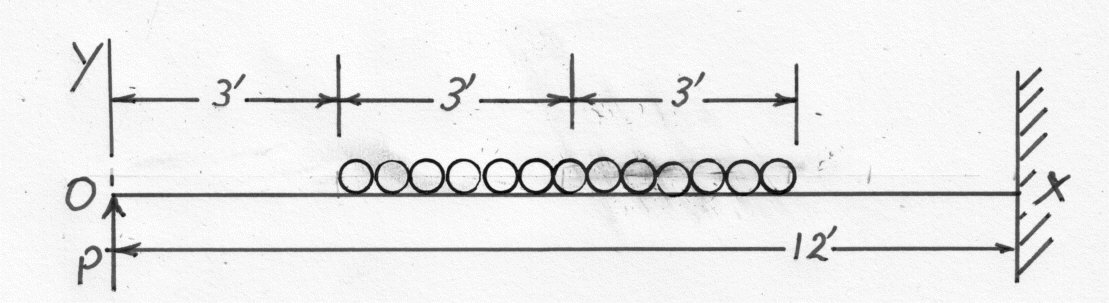
A cantilever 12 ft. long is supported at its free end by a prop at the same level as at the fixed end. A uniform distributed load of 2 tons/ft. is carried along the middle half of the beam, together with a central load of 5 tons. Determine the load at the prop and the maximum Bending Moment.
13108/img_mac_3.jpg
Blank

Let P be the load on the prop.

Taking the Prop as the origin (See equation 8)

E\,I\,\;\frac{d^2y}{dx^2}\;=\;Px\;-\;\frac{2}{2}[x\;-\;3]^2\;+\;\frac{2}{2}[x\;-\;9]^2\;-\;5[x\;-\;6]
(38)
E\,I\,\;\frac{dy}{dx}\;=\;P\frac{x^2}{2}\;-\;\frac{[x\;-\;3]^3}{3}\;+\;\frac{[x\;-\;9]^3}{3}\;-\;\frac{5[x\;-\;6]^2}{2}\;+\;A
(39)
E\,I\,\;y\;=\;P\frac{x^3}{6}\;-\;\frac{[x\;-\;3]^4}{12}\;+\;\frac{[x\;-\;9]^4}{12}\;-\;\frac{5[x\;-\;6]^3}{6}\;+\;A\;x\;+\;B
(40)
When\;\;\;x\;=\;12\;ft.\;\;\;\frac{dy}{dx}\;=\;0\;\;\;and \;\;\;y\;=\;0
(41)
\therefore\;\;\;\;\;\frac{dy}{dx}\;=\;72P\;-\;243\;+\;9\;-\;90\;+\;A\;=\;0
(42)
\therefore\;\;\;\;\;A\;=\;324\;-\;72P
(43)

Using Equations (40) and (43)

y\;=\;0\;=\;288\,P\;-\;720\;+\;12\,A\;+\;B
(44)

Substituting in the value for A

B\;=\;-\,288\,P\;+\;720\;-\;12\times324\;+\;12\times 72\,P:=;576\,P\;-\;3168
(45)

But when x = 0 y = 0 and therefore B = 0

\therefore\;\;\;\;\;\;P\;=\;\frac{3168}{576}\;=\;5.5\;tons
(46)

A point of maximum Bending Moment occurs at a value of x giving Zero Shear Force and this will be in the distributed load such that the downwards load equals the load on the prop. ( See " The relations between w; F and M" in the pages on Shearing Force and Bending Moments)

x\;=\;3\;+\;\frac{5.5}{2}\;=\;5.75\;ft. \;\;\;from\;the\;Prop
(47)
Where\;\;\;\;\;M\;=\;5.5\times5.75\;-\;\frac{2}{2}(5.75\;-\;3)^2\;=\;24.1\;tons-ft.
(48)

Note the fraction 2/2 is w/2 where w is the uniform loading.

Check this result against the value at the built in end.

M\;=\;5.5\times12\;-\;1\times(12\;-\;3)^2\;+\;1\times (12\;-\;9)^2\;-5(12\;-\;6)
(49)
\therefore\;\;\;\;\;M\;=\;36\;tons-ft
(50)

The greatest Bending Moment is therefore 36 tons-ft.

Example 4

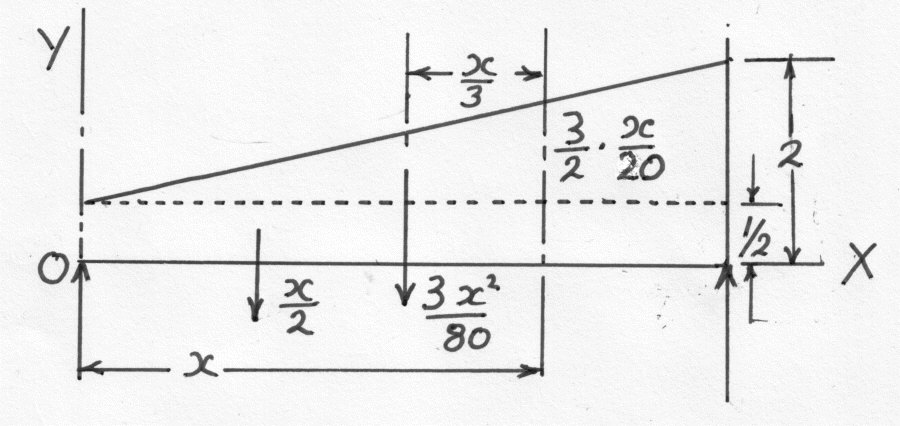
A horizontal beam simply supported at its ends, carries a load which varies uniformly from 1/2 tons/ft. at one end to 2 tons/ft at the other. Estimate the central deflection if the span is 20 ft, the section 18 inches deep and the Maximum Bending Stress is 6 tons/sq. in. Take E as 13400 tons/sq.in. (U.L.)

Divide the loading diagram into a uniform rate of 1/2 tons/ft. and a varying load ( from 0 to 3/2 tons/ft.) which has the following value x ft. from the end.
13108/img_mac_4.jpg
Varying\; Load\;=\;\left(\frac{3}{2} \right)\left(\frac{x}{20} \right)\;=\;\frac{3\,x}{40}\;tons/ft.
(51)

Let R be the reaction at the support as shown.

Taking Moments about the other support:-

20\;R\;=\;\left(\frac{1}{2}\times20 \right)\times10\;+\;\left(\frac{1}{2}\times\frac{3}{2}\times20 \right)\times\frac{20}{3}
(52)

where the varying load has a total value given by the mean intensity times the span and acts at the centroid of the triangular figure.

\therefore\;\;\;\;\;R\;=\;10\;tons
(53)

Repeat the same method to obtain an expression for the Bending Moment at a distance x from the support.

E\,I\,\frac{d^2y}{dx^2}\;=\;10x\;-\;\frac{1}{2}\frac{x^2}{2}\;-\;\left[\frac{1}{2}\left(\frac{3x}{40} \right)x \right]\;\frac{x}{3}
(54)
\;therefore\;\;\;\;\;\;\;E\,I\,\frac{d^2y}{dx^2}\;=\;10x\;-\;\frac{x^2}{4}\;-\;\frac{x^3}{80}
(55)
Integrating\;\;\;\;\;\;\;E\,I\,\frac{dy}{dx}\;=\;5x^2\;-\;\frac{x^3}{12}\;-\;\frac{x^4}{320}\;+\;A
(56)
Integrating\;again\;\;\;\;\;\;\;E\,I\,y\;=\;\frac{5x^3}{3}\;-\;\frac{x^4}{48}\;-\;\frac{x^5}{1600}\;+\;Ax\;+\;B
(57)

At x = 0 y = 0 and therefore B = 0

At x = 20 ft. y = 0

\therefore\;\;\;\;\;\;A\;=\;-\;\left(\frac{5\times20^2}{3} \right)\;+\;\frac{20^3}{48}\;+\;\frac{20^4}{1600}\;=\;-400\;tons-ft^2
(58)
Blank

The maximum Bending Moment will occur at zero shear force. Therefore differentiating equation (54)

\frac{d^3y}{dx^3}\;=\;0\;=\;10\;-\;\frac{x}{2}\;-\;\frac{3x^2}{80}
(59)
Or\;\;\;\;\;3x^2\;+\;40x\;-\;800\;=\;0
(60)

Giving x = 11 ft.

\hat{M}\;=\;10\times11\;-\;\frac{11^2}{4}\;-\;\frac{11^3}{80}\;=\;63.1\,tons-ft.
(61)

The Maximum Stress of 6 tons/sq.in. is given by:-

6\;=\;\frac{\left\{\hat{M}\times\left(\frac{1}{2}\;depth \right) \right\}}{I}
(62)
\therefore\;\;\;\;\;I\;=\;63.1\times12\times\frac{9}{6}\;=\;1135\;in.^4
(63)

At the centre

E\,I\,y\;=\;5\times\frac{10^3}{3}\;-\;\frac{10^4}{48}\;-\;\frac{10^5}{1600}\;-\;400\times10\;=\;-2604\,tons-ft^3
(64)
\therefore\;\;\;\;\;y\;=\;\frac{2604\times12^3}{13400\times1135}\;=\;0.296\.in.
(65)

Alternatively this problem could have been solved by commencing with the rate of loading equation:-

E\,I\,\frac{d^4y}{dx^4}\;=\;-\frac{1}{2}\;-\;\frac{3x}{40}
(66)

and then integrating twice to obtain the Bending Moment Equation. The constants of integration can be found from M = 0 at x = 0 and at x = 20 ft.

Example 5

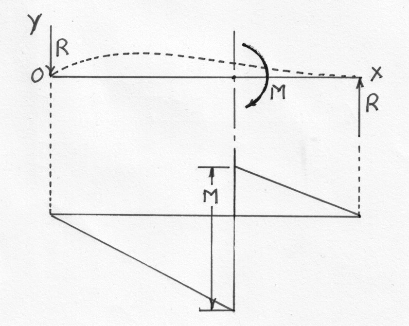
A beam which is supported by pin joints at its ends is acted upon by a couple M in the plane containing the axis of the beam. The couple is applied two thirds of the span from one end. Find an expression for the slope and deflection at the point of application and indicate the shape of the deflected beam.

The reactions must be equal and opposite \displaystyle i.e.\;\;\;\;R\;=\;\frac{M}{l}
13108/img_mac_5.jpg
Blank

The Bending Moment diagram is shown in the diagram giving:-

E\,I\,\frac{d^2y}{dx^2}\;=\;-Rx\;+\;M\left[ x\;-\;\frac{2l}{3} \right]^0
(67)
Integrating\;\;\;\;\;\;E\,I\,\frac{dy}{dx}\;=\;-R\frac{x^2}{2}\;+\;M\left[ x\;-\;\frac{2l}{3} \right]\;+\;A
(68)
Integrating\;again\;\;\;\;\;E\,I\,y\;=\;-R\frac{x^3}{6}\;+\;\frac{M}{2}\left[ x\;-\;\frac{2l}{3} \right]^2\;+\;Ax\;+\;B
(69)

When x = 0 y = 0 and therefore B = 0

When x = l y = 0

\therefore\;\;\;\;\;A\,l\;=\;\frac{R\,l^3}{6}\;-\;\left( \frac{M}{2} \right)\left(\frac{l}{3} \right)^3
(70)
Or\;\;\;\;\;A\;=\;\frac{Ml}{9}
(71)
At\;\;\;\;\;x\;=\;\frac{2l}{3}
(72)
E\,I\,\frac{dy}{dx}\;=\;-\,\left(\frac{R}{2} \right)\left(\frac{2l}{3} \right)^2\;+\;\frac{Ml}{9}\;=\;-\,\frac{Ml}{9}
(73)
i.e.\;\;\;\;\;\;Slope\;=\;-\;\frac{Ml}{9\,E\,I}
(74)

This indicates that the beam will slope downwards to the right.

E\,I\,y\;=\;-\,\left(\frac{R}{6} \right)\left(\frac{2l}{3} \right)^3\;+\;\frac{Ml}{9}\left(\frac{2l}{9} \right)
(75)

Thus the deflection is given by:-

y\;=\;\frac{2Ml^2}{81E\,I}\;\;\;\;\;\;upwards
(76)

There must be a point of zero slope for x < 2l/3 which is given by:-

-\;\frac{Rx^2}{2}\;+\;A\;=\;0
(77)
\therefore\;\;\;\;\;\;x\;=\;\left(\frac{ \sqrt{2}}{3}\right)l
(78)

The maximum deflection is given by:-

\hat{y}\;=\;\frac{\left[-\,\left(\frac{M}{6l} \right)\left(\frac{2\;\sqrt{2}}{27} \right)l^3\;+\;\left(\frac{Ml}{9} \right)\left(\frac{\sqrt{2}}{3} \right)l \right]}{E\,I}
(79)
=\;\frac{2\sqrt{2}\;M\,l^2}{81\,E\,I}
(80)
At\;x\;=\;l\;\;\;\;\;Slope\;=\;\frac{\left[-\,\left(\frac{M}{l} \right)\left(\frac{l^2}{2} \right)\;+\;\frac{Ml}{3}\;+\;\frac{Ml}{9} \right]}{E\,I}
(81)
=\;-\;\frac{Ml}{18\,E\,I}
(82)

So that the beam lies entirely "above" the OX axis. Its shape is similar to the dotted line on the diagram.