
Moments of Area
The calculation of deflections using Moments of Area
You're viewing an older version of this page (#3448). View the current version.
The drawing shows the Bending Moment diagram and the shape of a deflected beam between two point P and Q.
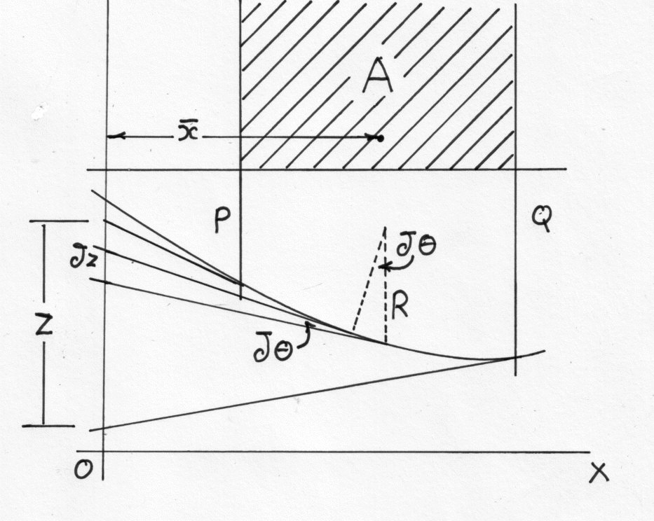
The area of the Bending Moment diagram is A and its centroid is at a distance of from a chosen line OY. The tangents at P and Q to the elastic line, cut off an intercept z on OY.
Integrating between P and Q
If EI is a constant then
i.e. The increase of slope between any two points on a beam is equal to the net area of the Bending Moment diagram between those two points divided by EI
If R is the radius of curvature of the beam at some point between P and Q, then the angle between the tangents at the end of a short length where
. The intercept of these tangents on OY is
and since the slope everywhere is small:-
Integrating
i.e. The intercept on a given line between the tangents to the beam at any two points P and Q is equal to the net moment about that line of the Bending Moment diagram between P and Q divided by EI
Account has to be taken of positive and negative areas and frequently it is convenient to break down the Bending Moment diagram into a number of simple figures, so that the moment is obtained from
The interecept z is positive when the tangent at Q strikes OY below the tangent at P.
This method is only used for particular applications in which it produces a quicker solution than the mathematical treatment. These cases can generally be labeled as those for which a point of zero slope is known. If this point is chosen as "Q"and OY is taken through P then equation (3)reduces to :
And equation (6) gives the deflection of P relative to Q as
i.e. The deflection at any point can be found by working between there and a point of zero slope and taking Moments about the point where the deflection is required
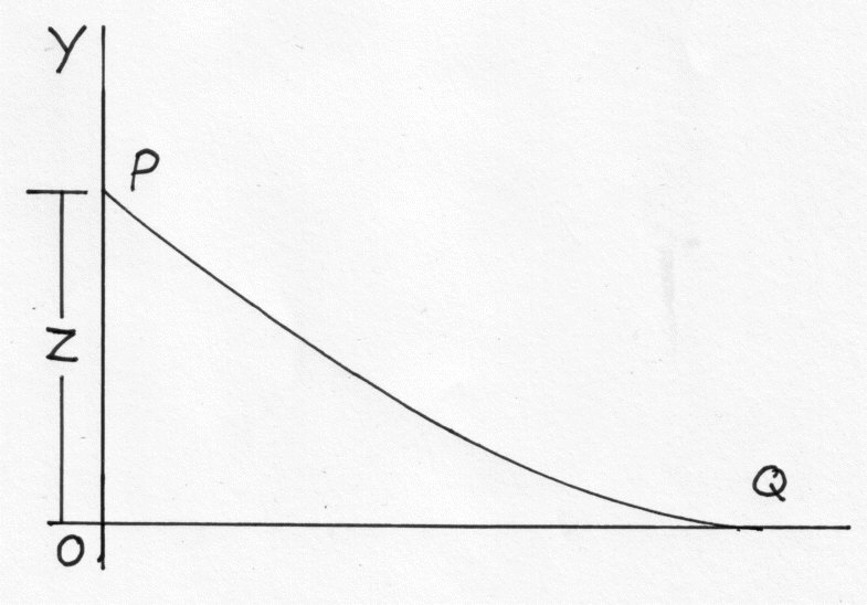
It is very helpful in applying these theorems to sketch the approximate shape of the deflected beam and then by drawing the tangents at chosen points it should be clear which intercepts gives the relative deflection
(e.g. If OY is taken through Q in the above diagram the intercept does not give the deflection}
Summarising the Cases in which this Method is useful,
- Most Cantilever cases ( Zero slope at the fixed end
- Symmetrically loaded simply supported beams ( The slope at the centre is zero)
- Built in Beams ( Zero slope at each ends
Uniformly distributed loads
For uniformly distributed loads the Bending Moment diagram is a parabola and the following properties of area and centroids should be known.
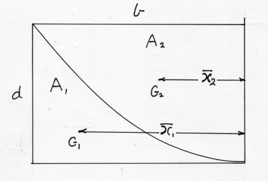
In the above diagram the surrounding rectangle has an area of bd. and the parabola is tangential to the base.
Then
Example 1
1 Obtain expressions for the maximum slope and deflection of a simply supported beam of span l with a) A concentrated load W at the centre and b) With a uniformly distributed load w over the whole length.
In both cases, by symmetry the slope is zero at the centre and the maximum slope and deflection can be found from the area of the Bending Moment diagram over half the beam. i.e. "P" is at the support and "Q" is at the centre of the beam.
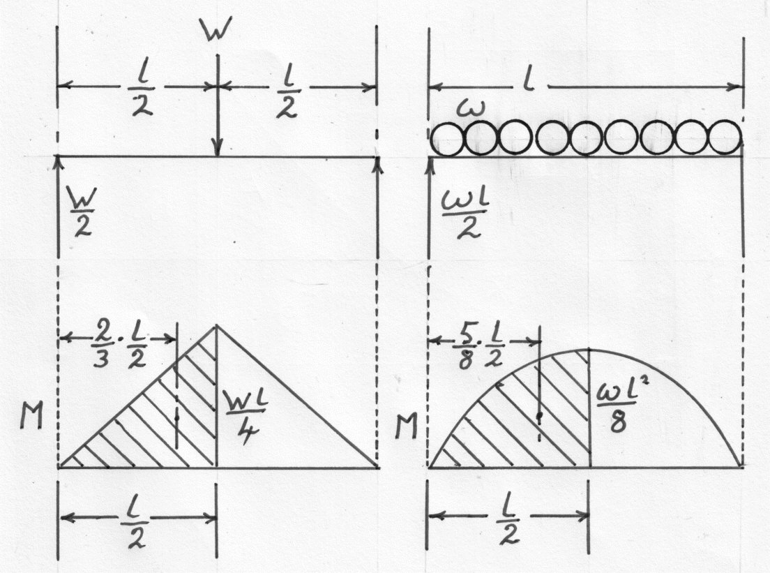
a) If A is the area of the Bending Moment diagram for half the beam then:
Using Equation (3)
From Equation (6)
The deflection of the support relative to the centre:
b) The area A of the shaded area of the Bending Moment diagram is given by:-
Using equation (3) as before:
From equation (6) the deflection of the support relative to the centre is given by:
Example 2
A horizontal cantilever ABC , 15ft long, is built in at A and supported at B 12 ft. from A, by a rigid prop so that AB is horizontal. If AB and BC carry uniformly distributed loads of 0.5 tons/ft. and 1.0 tons/ft. respectively, find the load taken by the prop (U.L.)
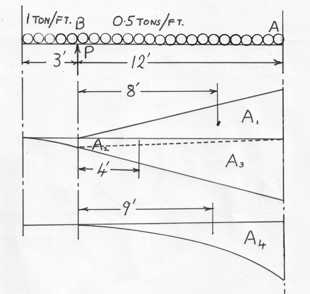
If the Bending Moment diagram is broken down into the areas shown in the diagram,each area can be dealt with as a triangle or parabola of standard type.
If P is the load on the prop then:
Due to the load on BC the Bending Moment at B is given by:-
And at A it is:
The trapezium between A and B can be split into two triangles
Due to the load on AB the area is a parabola with a maximum value of
The slope is zero at the built in end A anad the deflection is zero at B. Hence from equation (6)
For the portion AB about B
Substituting in values
Example 3
A horizontal beam rests on two supports at the same level and carries a uniformly distributed load. If the supports are symmetrically placed find their position when the greatest downward deflection has its least value. (U.L.)
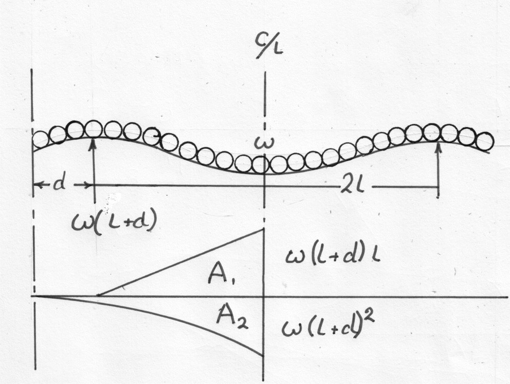
Let the distance between the supports be 2l and the overhanging distance d. The the reaction at each support
The condition for the greatest downwards deflection to have its least value occurs when the deflection at the ends and the centre are the same, since any variation of the supports from this position will increase either one or the other of these values. Since the slope is zero at the centre then for half the beam about one end
Breaking down the Bending Moment diagram into due to the support and
due to the load then:-
i.e.
From which by trial and error
Example 4
A long steel strip of uniform width and thick is laid on a level floor, but passes over a 2 in. roller lying on the floor at one point. For what distance on either side of the roller will the strip be clear of the ground and what will be the maximum stress induced?
Take the density of steel to be
For that part of the strip lying on the floor, the reaction balances the weight and since there is no change of slope, there is no Bending Moment in this length. However where the strip leaves the floor there will be a point reaction R and the conditions as if the surplus length had been cut off.
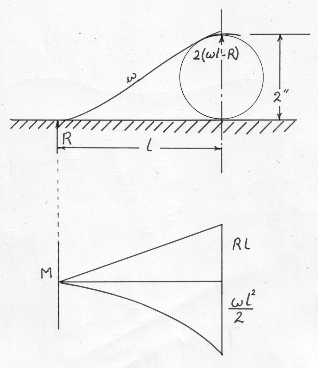
The forces and Bending Mare shown in the diagram. w is the weight of strip per unit length.
Since there is no change of slope between R and the top of the roller, equationg the areas gives:-
Using equation (6) and substituting values from the B.M.diagram
Substituting in values and putting the width of the strip as p
Equation (36) can also be obtained by treating the roller as a "fixed end" and taking the difference between the "cantilever" deflections due to R and w.
The maximum Bending Moment is at the roller and by using equation (3) we can solve (numerically) to obtain:
There is point of zero shearing force at l/3 from R but here
Example 5
A cantilever of uniform strength is to be turned from a mild steel bar 2 inches in Diameter. A load of 1000 lb. is to be supported from the free end and the maximum stress is limited to 10,000 lb/sq.in. Determine the maximum length of the cantilever and its end deflection.
(U.l.)
Note The finished cantilever is tapered.
The maximum Bending Moment is 1000 lat the fixed end and the strongest section is 2 in. diameter. Applying the Bending Stress formula.
Let the diameter be d at x in. along the bar from the fixed end, then applying the condition for uniform strength ( i.e. Constant maximum Stress)
The I value is varying along the bar but the deflection can be found by the Moment-area Method. using the form .
Z gives the end deflection if Moments are taken about the free end i.e.
Substituting for d from equation (44)