
Deflection Coefficients
Deflection is a term that is used to describe the degree to which a structural element is displaced under a load.
A cantilever is a beam anchored at only one end. The beam carries the load to the support where it is resisted by moment and shear stress. Cantilever construction allows for overhanging structures without external bracing.
A beam is a horizontal structural element that is capable of withstanding load primarily by resisting bending. The bending force induced into the material of the beam as a result of the external loads, own weight, span and external reactions to these loads is called a bending moment.
This section covers deflection coefficients, including deflection due to shear and the use of graphical methods.
You're viewing an older version of this page (#3929). View the current version.
The Method of Deflection Coefficients.
It can be seen that any beam of length and flexural rigidity
which carries a load
(no mattter how it is distributed), will have a maximum deflection of
; where
is a constant which depends upon the type of loading and supports.
The value of has been found for the standard cases of a cantilever and a simply supported beam (See Deflection of Beams Part 1 Example 4 and Part 3 Example 1), and the deflection in other cases may frequently be built up by superposition.
The Principle of Superposition: This states that where a number of loads act together on an elastic material, the resulting strain is the sum of the individual strains caused by each load acting separately.
Two types of problems will be solved by this method:
Example 1 [imperial]
A beam of uniform section and length is simply supported at its ends and by an elastic prop at the centre. If the prop deflects an amount
times the load it carries and the beam carries a total uniformly distributed load
show that the the load carried by the prop
If
and
Find the position and value of the maximum Bending Moment.
If is the load on the prop, then its deflection is
carries a uniformly distributed load of 5 tons over its length of 10 ft. The beam is supported by three vertical steel tie rods each 6 ft. long, one at each end and one in the middle, the end rods having diameters of 1 in. and the centre rod 1.25 in.
Calculate the deflection at the centre of the beam below the end points and the stress in each tie rod.
The downwards deflection due to the load only is :
The upwards deflection due to the prop only is:
By superposition, the net downwards deflection is given by:
Thus,
Substituting the numerical values given:
The reaction at the end supportsis given by:
And for
,
For a maximum
And
- The deflection is
- The value of the maximum Bending Moment is
Example 2 [imperial]
A horizontal steel beam, carries a uniformly distributed load of 5 tons over its length of 10 ft. The beam is supported by three vertical steel tie rods ech 6 ft. long, one at each end and one in the middle, the end rods having diameters of 1 in. and the centre rod 1.25 in.
Calculate the deflection at the centre of the beam below the end points and the stress in each tie rod.
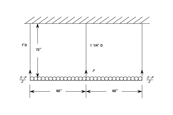
Let tons be the load at the centre of the rod. Then by superposition the following equation can be written:
Stretch of centre rod - stretch of end rod = Deflection of beam due to load - deflection due to centre rod.
Substituting given values:
Thus,
The stress in the centre rod
Stress in an end rod
The deflection of the centre of the rod relative to the ends is given by the difference of stretches of the tie rods. This equals:
NB:
- The stress in the centre rod is
- The stress in an end rod is
- The deflection at the centre of the beam is
Deflection due to Shear
It can be shown that the shear stress set up in the transverse section of a beam and the accompanying shear strain will cause a distortion of the cross-section. Since the shear stress varies from zero at the extreme fibres to a maximum at the neutral axis, cross sections can no longer remain plane after bending.
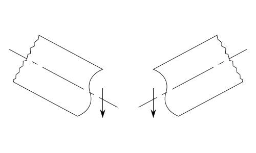
In fact the "warping" will be of the form shown in the diagram. The left-hand view being for positive shear and the right-hand for negative shear. These strains are incompatible with the theory of pure bending, but nevertheless a good approximation in deflection can be obtained by strain energy methods. It should also be noted that the shear distribution near to the application of a concentrated load must differ considerably from that given by the theory, since there can be no sudden change of shear strain from one type to the other, as would be implied for a simply supported beam with a central load.
Strain Energy due to Shear
And for the whole beam:
where is an element of cross-section and
an element of the length.
The integration can only be performed for a particular cross-section over which the variation of is known and rectangular and
-sections will be calculated.
Rectangular Section
It can be shown that using equation (#1)
For a Cantilever with a load of W at the free end W = F
Thus from equation (#2),
If is the deflection due to shear, then
For a Cantilever with a uniformly distributed Load.
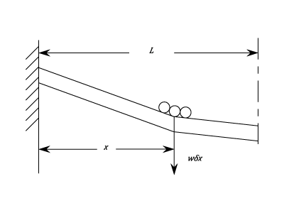
A load acting on a length
(situated at a distance
from the fixed end) will produce a deflection due to shear at this point of
. For this load alone the distortion produced is indicated in the diagram, and is uniform for the shear force over the length
and zero over the rest of the beam
. Hence the total deflection due to shear for all the distributed load is given by:
For a Simply Supported Beam with Central Load W
Thus by using equation (#2) again,
But since,
By substitution in equation (#3 )
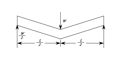
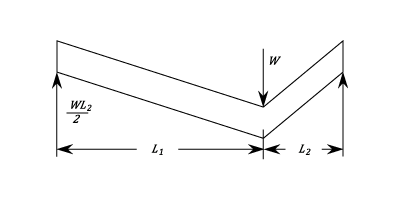
The simplified deflection is as shown in the upper diagram and since the shearing force is constant over each half, this case is equivalent to a cantilever of length carrying an end load of
.
If the load is not centrally applied but divides the length into and
, then we can treat either end as a cantilever with an end load equal to the reaction on that side.
Hence,
A Simply supported Beam with A Uniformly Distributed Load
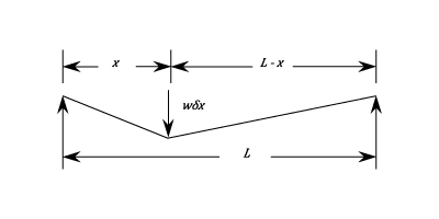
Considering a load only at a distance
from one end
the deflection at the load will be:
Note this has already been proved in equation (#4)
By proportion the deflection at the centre of the beam :
Then the total central deflection due to shear is:
I-section
The shear force is treated as being uniformly distributed over the web area.
Thus and
and using equation (#1)
By similar methods to those used from a rectangular section the deflections due to shear may be obtained as follows:
- Cantilever with end load
- Cantilever with distributed load
- Simply supported beam with central load
- Simply supported beam with distributed load
The Strain Energy method known as Castigliano's Theorem (See Bending of Curved Bars) may be used where a number of loads exist concurrently, or to find the distributed load by imposing a concentrated load at a deflection point; the latter giving it a value of zero. i.e.
Example 1 [imperial]
For a given cantilever of rectangular cross-section, length and depth
show that if
and
are the deflections due to shear and Bending due to a concentrated load at the free end,
and find the value for
for steel.
.
Hence find the least value of if the deflection due to shear is not to exceed 1% of the total.
It has been shown that:
For a rectangular Section:
If
Then
The least value of
is
- The least value of
is
Example 2 [imperial]
A 10 in. by 6 in. R.S.J. with web 0.4 in. , flanges 0.7 in/ thick acts as a horizontal cantilever 12 ft. long and carries a load of 2 tons at 6 ft. from the end and assuming that the shear force is carried by the web and is uniformly distributed, calculate the deflection at the end.
and
Using the Moment of Area method ( See Deflection of Beams Part 3) the end deflection due to bending is given by:
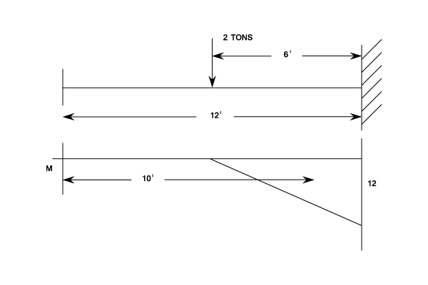
The Deflection at the load due to Shear is:
Since the shear force is zero beyond the load there is no further deflection due to shear between the load and the end of the beam.
Thus the deflection at the end of the beam is the result of both bending and shear and is:
- The deflection at the end is
Deflection by Graphical Method
It was shown in the pages on "Shearing force and Bending Moment" that a Funicular Polygon could be used to perform a double integration of the load curve and this would produce the Bending Moment diagram.
Since , it follows that a double integration of the Bending Moment curve will
produce the Deflection Curve.
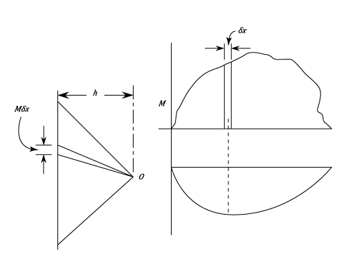
If is constant, draw the B.M. diagram and divide it into a number of strips of width
. Now draw a vertical line to represent the areas
and join this to a pole
on the right of the line. Proceed in the normal way to draw the funicular polygon, which will be a series of straight lines to be smoothed out into a curve.The vertical ordinates on this diagram represent deflection and it will usually be necessary to slew the diagram through an angle in order to produce a horizontal base (e.g. from a simply supported beam)
If the scales are and
, then the distance
is given by
If then the Deflection scale required is