
Built in Beams
The bending of Built in Beams fixed at both ends.
You're viewing an older version of this page (#3933). View the current version.
Introduction
A Beam is said to be Built-in or 'encastre' when both ends are rigidly fixed so that the slope remains horizontal - It is normal for both ends to be at the same level. In other words, it is assumed that built in beams have zero slope at each end, and therefore the total change of slope along the span is zero.
In general terms, all other geometrical aspects remaining the same, a built in beam is considered stronger than a http://codecogs.izyba.com/reference/engineering/materials/beams/2445.php?showv=1 "simply supported beam" . As built in beams are statically indeterminate, techniques such as linear superposition are often used to solve problems associated with them. The bending moment for a loaded built in beam is normally maximum at the end joints.
In this section we look at the Moment-Area method, and the Macaulay method (calculus method) to calculate the fixing moments and the end reaction.
Moment-Area method for Built in Beams
It follows from the Moment-Area method (See Bending of Beams Part 3) that since the change of slope from end to end and the intercept are both zero, then:
and,
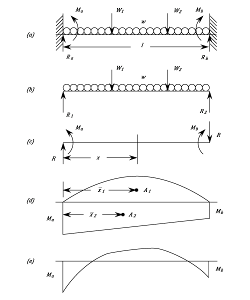
It is easier to consider the Bending Moment diagram for the Built in Beam in the diagram as the algebraic sum of two parts. The first considers the beam to be Simply Supported (b), and the second, due to the end moments which must be introduced to bring the slopes back to zero (c). The area and end reactions obtained, if freely supported, will be referred to as The Free Moment Diagram and the Free reactions ,
and
.
The Fixing Moments at the ends are and
and in order to maintain equilibrium when
and
are unequal, the reactions
are introduced. These are upwards on the left-hand end and downwards on the right.
Due to ,
and
the Bending Moment at a distance
from the left-hand end is given by:
This gives a straight line going from a value of at
to
at
. From this can be drawn the Fixing Moment Diagram
(See d).
For the downward loads is a positive area (Sagging
) and
is a negative area (Hogging
). Consequently, equations (#1) and (#2) reduce to:
And
(Numerically)
These give rise to two important statements:-
- Area of the Free Moment Diagram = Area of the Fixing Moment Diagram.
- The Moments of Areas of Free and Fixing Diagrams are equal.
It may be necessary to break down the areas still further to obtain convenient triangles and parabolas.
These two equations allow and
to be found and the total reactions at the ends are :
And
The Combined Bending Moment Diagram (e) is the Algebraic sum of the two components.
Example 3 [imperial]
A built-in beam of span 12 ft. carries a uniformly distributed load of half a ton per foot over its whole length. There are also concentrated loads of 2 tons at 3 ft. and 3 tons at 8 ft. from one end.
If the Bending Stress is limited to 6 tons/sq.in, calculate the section Modulus required and sketch the Bending Moment diagram.
For each concentrated load and
(see equations (3) and(4)- Example 2) and for the distributed load
By combination, Total
Total
The maximum Bending Moment is thus
The Section Modulus = (note change from ft. to in.)
The following combined Bending Moment diagram has been built up from its component parts and the main values are shown.
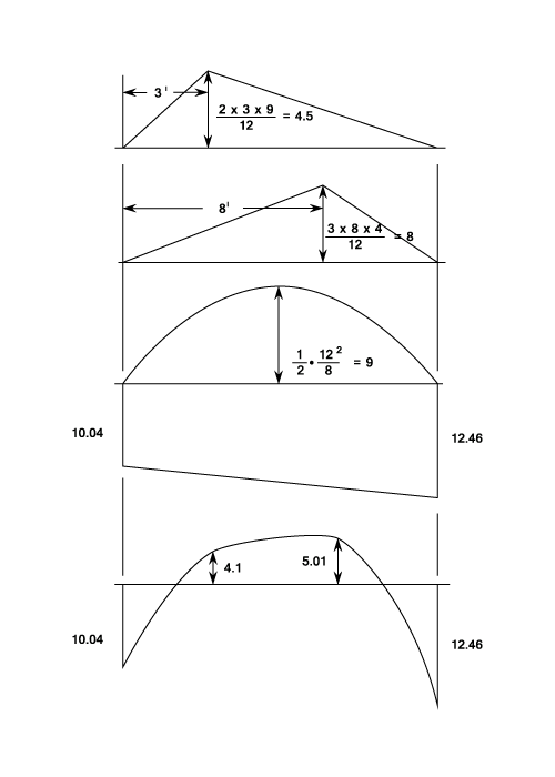
The effects of complete and perfect end fixings are to reduce the maximum Bending Moment ( and hence the Stress) and to reduce the deflection, as may be appreciated from the previous examples. In Practice it is almost impossible to ensure no change of slope at the ends, so that usually the degree of fixing is both imperfect and indeterminate. A rotation of the ends proportional may be allowed for and this is shown in the next example where the stiffness of the built in ends has been estimated empirically.
A further practical problem is the danger of settlement of one end relative to the other. This produces an appreciable change in the value of the fixing Moment.
- The Section Modulus is
Example 4 [imperial]
A rung of a vertical ladder is in a horizontal plane and has the form of three sides of rectangle, the short sides of length and the long side
. The rung is made of steel of circular section and the short sides are securely built in to the vertical sides of the ladder.
If a vertical load is carried in the middle of the long side, find the twisting Moment on each of the short sided in terms of
and
.
And
Let be the twisting Moment on each of the short sides. This then acts as a Bending Moment on each end of the long side and if
is the angle of twist of the short sides it is also the angle of slope of the long side.
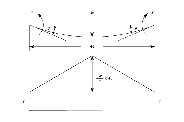
For the Twisting of a short side:
Or
Treating the long side as a centrally loaded beam with incomplete fixing moments . The increase in slope from end to end is
Thus
Equating (#1) and (#2) and noting that
From Which:
Example 5 [imperial]
Find an expression for the change of Fixing Moments and the End Reactions when one end of a built in Beam of span sinks by an amount
below the other. The ends remain horizontal.
If is the change in Fixing Moment it must be hogging at one end and sagging at the other. The change in end reactions
must be given by
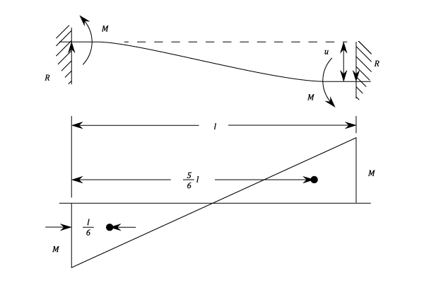
The Bending Moment is shown in the diagram.
since
And
Alternatively this question can be solved by treating it as two Cantilevers of length carrying end loads of
.
Hence
And as before
Macaulay Method
When the Bending Moment diagram does not lend itself to simplification into convenient areas, it may be quicker to use the calculus method (See Bending of Beams Part 3). This also has the advantage of giving the Fixing Moments and end Reactions directly, and enables the maximum deflection to be found.
Example 1 [imperial]
A Beam of uniform Section is built in at each end and has a span of 20 ft. It carries a uniformly distributed load of on the left hand half together with a 12 ton load at 25 ft. from the left hand end.
Find the end reactions and Fixing Moments and the magnitude and position of the maximum deflection.
and
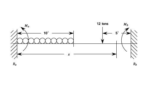
Taking the Origin at the left hand end and let the Fixing Moments be and
. The Reactions
and
.
Then
Integrating,
When
Integrating,
When
Also when
and
Subtracting equation (#2) from (#1)
Thus,
From equation (#1)
But = Total downwards Load =
And = Value of
at
Since the concentrated load is greater than the total concentrated load and acts at an equal distance from the nearest end, it may be deduced that zero slope occurs at a value between 10 and 15 ft.
Solving this quadratic gives:
Substituting this value in the deflection equation gives:-
Thus the maximum deflection is given by: