
Compound Stress and Strain Part 2
A diameter of a circle is any straight line segment that passes through the center of the circle and whose endpoints are on the circle. The diameters are the longest chords of the circle.
A shear stress is defined as the component of stress coplanar with a material cross section. Shear stress arises from a force vector perpendicular to the surface normal vector of the cross section.
Shear strain refers to a deformation of a solid body in which a plane in the body is displaced parallel to itself relative to parallel planes in the body; quantitatively, it is the displacement of any plane relative to a second plane, divided by the perpendicular distance between planes.
A description of Mohr's Stress and Strain Circles, two and three dimensional Stress and Strain systems, and Strain Energy.
You're viewing an older version of this page (#3921). View the current version.
Introduction
This is the second part in our discussion on the topic of Compound Stress and Strain. In this section we analyse the state of Stress at a point with a graphical representation using Mohr's Circle. In the latter half, we also look at how Mohr's circle can be adapted to represent direct or linear strain, and shear strain.
See Also the section on http://codecogs.izyba.com/reference/engineering/materials/2433.php?showv=1 "Compound Stress and Strain Part 1" .
Mohr's Stress Circle
Mohr's circle is a two-dimensional graphical representation of the state of stress at a point. The abscisa and ordinate of each point on the circle are the normal stress and shear stress components respectively, acting on a particular cut plane with a unit vector with components
,
,
. In other words, the circumference of the circle is the locus of points that represent the state of stress on individual planes at all their orientations.
Mohr's Stress Circle allows the Stress on any plane which makes an angle with the Principle Planes.
In the figure and
are the Principle Stress on the Principle Planes
and
.
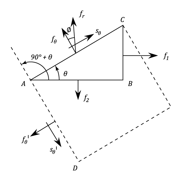
To draw the circle:
- Draw a line
such that
represents
and
. Note that the positive direction (Tension) is to the right.
- On
as a Diameter draw a Circle with centre
- On this drawing
, but this is not a necessary condition.
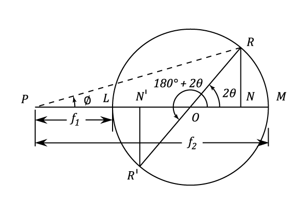
- The radius
represents the plane of
- The radius
represents the plane of
- The Plane
is obtained by rotating
through
and if
in the same direction, then the radius
is obtained. This will be shown to represent the plane
corresponding to rotating
clockwise through
)
- Draw
perpendicular to
Then,
is the normal Stress Component on
(See Part 1 of Compound Stress and Strain).
And
where
is the Shear Stress Component on
Also, the Resultant Stress is given by:
The inclination of the resultant Stress to the Normal of the plane is given by:
is a Tensile Stress in this case and
is considered positive if
is above
. A positive Shear Force is one which tends to give a clockwise rotation to a rectangular element (Shown dotted in the first Diagram).
- The Stresses on the plane
, perpendicular to
to
i.e., and
,
the latter being of the same magnitude as
but of the opposite type which tends to give an anticlockwise rotation to the dotted element.
- The Maximum Shear Stress occurs when
(i.e.
) and is equal in magnitude to
- The maximum Value of
is obtained when
is a tangent to the Stress Circle.
Two particular cases which were considered analytically in Part 1 are now dealt with using this method.
Pure Compression.
If is a Compressive Stress then the other Principle Stress is zero.
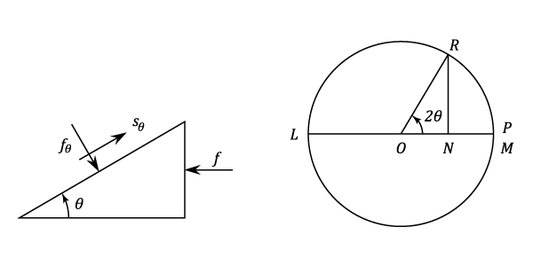
If is the angle measured from the Plane of zero Stress then in the above diagram
numerically. It will be measured to the left for Compression.
Hence:
Compressive
Positive
And the Maximum Shear Stress occurs when
and is given by:
Principal Stresses equal Tension and Compression.
Let be the angle measured anticlockwise from the Plane of
Tensile.
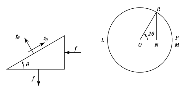
to the right.
to the left.
Hence coincides with
.
and is Tensile for
between
and Compressive for
between
and
.
. When
reaches its maximum value (Numerically equal to
) on those Planes where the Normal Stress is Zero (i.e. Pure Shear).
Example 1 [imperial]
A piece of material is subjected to two compressive Stresses at right angles, their values being and
Find the position of the Plane across which the resultant Stress is most inclined to the Normal and determine the value of this resultant Stress.
In the left hand diagram the angle is inclined to the plane of
compression. In the right hand diagram
and
. The maximum angle
is found when
is a tangent to the Stress Circle.
and
.
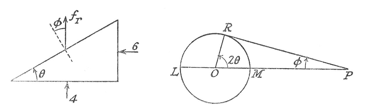
From the right hand diagram:
which gives the position of the plane required.
It is also possible to use Mohr's Stress Circle in the reverse sense to find the magnitude and direction of the Principal Stresses in a given Stress system. An example of this is shown below.
Example 2 [imperial]
At a point in a piece of elastic material there are three mutually perpendicular planes on which the Stresses are as follows: Tensile Stress and Shear Stress
on one plane, Compressive Stress
and Complementary Shear Stress
on the second plane and no Stress on the third plane.
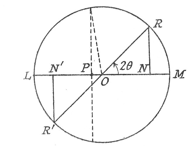
Find:
- a) The principal Stresses and the positions of the planes on which they act.
- b) The position of the planes on which there is no Normal Stress.
Construction:
- Mark off
,
,
,
- Join
cutting
at
- Draw circle Centre
and radius
- a) The Principal Stresses are:
Tensile
And Compressive
Also
This means that the Plane of the Tensile Principal Stress must be rotated through in an anti clockwise direction in order to coincide with the plane of
tensile Stress .
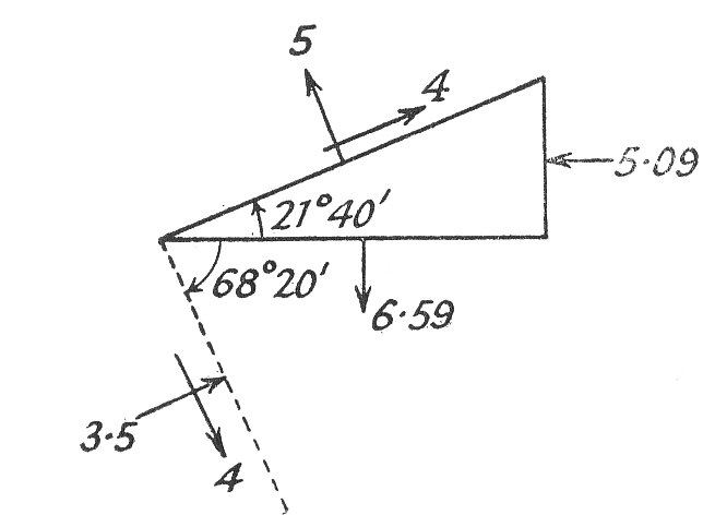
The relative position of the Planes is shown in the above diagram.
- b) If there is no Normal Stress then the plane
and
coincide and :
(The dotted radius on the previous diagram)
Therefore, to the Principal Plane
The following example gives a method of constructing Mohr's circle and hence finding the Principal Planes and Stresses when the Direct Stresses in any three directions is known.
- a) The principal Stresses are
Tensile
and Compressive
- b)
Example 3 [imperial]
Figure (a) shows the Direct Stresses in three directions which occur at a particular Point. It is required to find the Magnitude and Directions of the Principal Stresses.
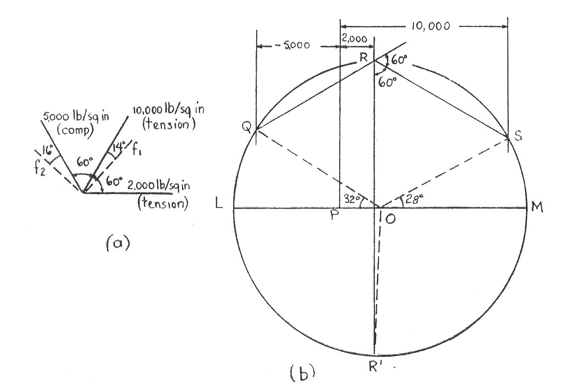
- Draw a vertical line (i.e. the one through
- At these distances draw three vertical lines, one for each Stress.
- Choose an arbitrary point on the central line and draw lines at
and
to the vertical cutting the other two verticals at
and
.
- The angles should be drawn so that they produce a similar figure to that produced by the Stress directions . i.e. It must be possible to rotate figure (a) and place it over
with the
Stress in the vertical position. The
vertical at
is produced (backwards in this case) to cut the
vertical at
- The circle which passes through
is constructed by using the perpendicular bisectors of the lines
and
. This Circle is Mohr's Stress Circle.
- The Stress conditions on the three given planes are related to the points
and
The justification for this construction lies in the fact that the angle at the centre of a circle is twice that the circumference and it can be seen that the angles between the radii ,
and
are
which is twice the angle between each pair of given Direct Stresses.
The Principal Stresses are given by :
and
is inclined at
i.e.
to the
Stress
And is inclined at
i.e.
to the -
Stress
A two-dimensional Stress System.
It has been shown that every system can be reduced to the action of pure normal Stresses on the Principal Planes.
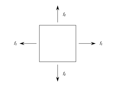
Consider the Strains produced by each Stress separately:
will cause:
- Strain
in the direction of
- Strain
in the direction of
will cause:
- Strain
in the direction of
- Strain
in the direction of
Since the Strains are all small, the resultant strains are given by the algebraic sum of those due to each Stress separately, i.e.,
- Strain in the direction of
- Strain in the direction of
The normal conventions apply and Tensile Stress is positive and Compressive Stress negative. A positive Stress represents an increase in dimensions in that direction.
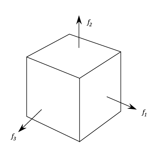
Principal Strains in Three dimensions.
Using a similar argument to that used in the previous paragraph t can be shown that the Principal Strains in the direction , and
are given by :
- (1)
- (2)
- (3)
It must be remembered that Stress and Strain in any given direction are not proportional when Stress exists in more than one dimension.
Strain can exist without Stress in the same direction (e.g. If , Then
).
Example 1 [imperial]
A piece of material is subjected to three perpendicular Tensile Stresses and the Strains in the three directions are in the ratio of 3:4:5.
If Poisson's Ratio is 0.286 find the ratio of the Stresses and their value if the greatest is
Let the Stresses be , and
and the corresponding Strains
,
, and
.
Then :
Subtracting Equation (#1) from (#3)
Re-writing equations (#3) and (#2)
And
From Equations (#4) and (#5)
From this and the other equations above :
Hence the Ratios of the stresses are:
If the greatest Stress is
Then ,
and
- The ratio of the Stresses are
,
and
Principal Stresses determined from Principal Strains.
Rearranging equations (#1),(#2) and (#3) as:
Subtracting Equation (#5) from (#4)
From (#4) and (#6)
Subtracting (#7) from (#8)
Similarly,
And,
(b) A Two Dimensional Stress System where
Solving these two equations for and
And,
Analysis of Strain.
If and
are the linear and Shear Strains in the plane
, then we require an expression for
, the linear Strain in a direction inclined at an angle
to
in terms of
and
.
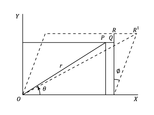
In the diagram the line , of length
, is the diagonal of a rectangle which under the given Strains distorts into the dotted parallelogram.
moves to
. It must be remembered that the actual Strains are small.
(Approx.)
But by definition
The Principal Strains and
are the maximum and Minimum values of Strain. These occur at values of
obtained by equating
to Zero,i.e.,
Then as for the Principal Stresses and
are given by :
In order to evaluate and
(and hence the Principal Strains) it is necessary to know the linear Strains in any three directions at a particular point.
(Note: If the principal direction are known then only two Strains are required,since and
,
).
Finally,if the Strains are caused by Stresses in two dimensions only, then the Principal Stresses can be determined by equations (#9) and (#10).
Mohr's strain Circle.
It is now apparent that Mohr's Circle can also be used to represent Strains. The horizontal axis represents linear Strain and the vertical axis half the Shear Strain.
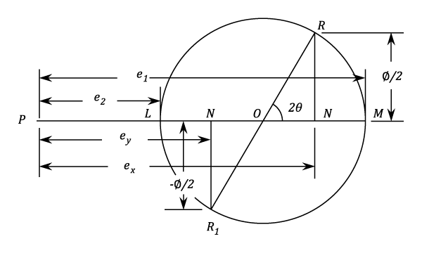
The diagram shows the relationship between and
and the Principal Strains
and
as given by equations (#11) and (#13).
Note that and
The Strain Circle can be constructed if the linear Strains in three directions at a point and in the same plane are known. The problem of the last exercise will now be solved using this method.
The given Strains are . The Construction of the circle is similar to the Stress Circle. Vertical lines are drawn in relative positions to a datum through
and at distances on either side proportional to the given Strains. From
on the central line (i.e.
in this case),lines are set off at
and
to the vertical, to cut the corresponding Strain Verticals in
and
. The Strain Circle then passes through
and the Principal Strains are :
And
The radius gives the Strain condition in the
direction and the angle
. The direction of
is then at
clockwise from the
-axis and
is at right angles to
.
The Principal Stresses can best be obtained from the Principal Strains by using the same calculations as were used in the last Example.
Volumetric Strain.
A rectangular solid of sides ,
,
is under the action of three principal Stresses
, and
.
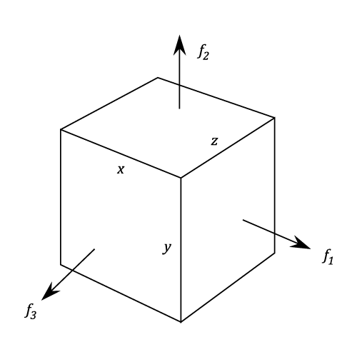
Then if , and
are the corresponding linear Strains, the dimensions become :
, and
The Volumetric Strain = Increase in volume / Original volume
Since the actual Strains are small this may be written as equal to:
Thus it can be stated that the Volumetric Strain is the Algebraic sum of the three Principal Strains.
The Volumetric Strain can also be found using the Principal Stresses in which case:
Volumetric Strain =
Strain Energy
The Strain Energy is the Work done by the Stresses in Straining material.It is sufficiently general to consider a unit cube acted upon by the three Principal Stresses
, and
. If the corresponding Strains are
, and
then, since the Stresses are applied gradually from zero, the Total work done =
.
Using equations (#1),(#2),(#3)
For a two dimensional Strain system
Example 1 [imperial]
The Principal Stresses at a point in an elastic material are tensile
tensile
compressive.
Calculate the volumetric Strain and the resilience.
and
Using equation (14), Volumetric Strain,
Resilience =
- The volumetric Strain is
- The resilience is
Shear Strain Energy.
Writing,
Then under the action of the mean stress there will be volumetric Strain with no distortion of shape (i.e.no shear Stress anywhere).
The Strain energy under this mean Stress acting in each direction can be derived from equation (#15) and may be called volumetric Strain Energy
The other terms in the arrangement of , and
are proportional to the maximum Shear Stress values in the three planes and will cause a distortion of the shape.
Shear strain Energy is defined as the Total Strain Energy and the Volumetric Strain Energy.
Thus,
The quantities in the brackets are each twice the maximum Shear Stress in their respective planes.
In a pure Shear Stress system the Principal Stresses are and by substitution:
Shear Straing Energy
Note: The relationship between and
will be discussed in "Elastic Constants".