
Mechanisms
An intoduction to the theory of Machines which includes instantaneous centres, friction circle,and Hookes Joint and other worked examples.
You're viewing an older version of this page (#3540). View the current version.
Introduction
This submission, the first in a number planned for "The Theory of Machines" introduces Forces in Mechanisms; Friction including The Friction Circle; The concept of Instantaneous Centres and velocities within a Mechanism. An analysis of Hooke's Universal Coupling is given. In addition a number of worked examples are included to illustrate the theory.
In order to study The Theory of Machines it is necessary to understand what is meant by a machine. In simple terms it is a contrivance which receives energy in some available form and uses it to do some particular kind of work. A crowbar together with its fulcrum forms a machine which enables the muscular energy of a man to raise a heavy weight. An Internal Combustion energy converts the chemical energy of the fuel produce motion or mechanical work and a lathe is a machine which uses electrical energy to remove metal from the work piece. It is also necessary to know and understand the terms used in this subject.
Definitions
- Each part of a machine which has motion relative to another part is termed An Element or Link. It is important to realise that an element may consist of several separate components which fixed rigidly together. (e.g. The connecting rod of an engine complete with the bearings and end caps and bolts is one element)
- A kinematic Pair This is when two bodies are in contact and there is relative motion between them. If the motion is one of sliding between surfaces in contact ( e.g. cross-heads in guides; Shafts in bearings; A screw and nut) it is known as A lower Pair When the contact takes place along a line ( e.g. a Cam and follower or toothed gearing) it is called A higher pair
- A kinematic Chain is a combination of Kinematic Pairs which have been so joined together that the relative motion between the Elements is completely determined.
- A Mechanism is obtained if one link of a Kinematic Link is fixed.. Differing Mechanisms may be obtained by fixing different different elements of the same chain. These are called inversions . For example The slider-crank chain( Engine Mechanism) becomes an oscillating-cylinder mechanism if the original "connecting-rod" is fixed, or a Whitworth "Quick-return mechanism if the "crank becomes the fixed link.
Instantaneous Centre
At any particular moment the motion of a body moving in a plane can be defined as pure rotation about a point known as The instantaneous centre of rotation. If is the angular velocity of the body and I is the instantaneous centre of rotation , the the velocity at any point P on the body is
in a direction perpendicular to IP.
With the exception of Bodies which are rotating about fixed centres, the Instantaneous Centre will be a point moving relative to the body. When the directions of Motion of two points on a Body are known, the Instantaneous Centre is at the intersection of lines through the points perpendicular to these directions.
The Relative Instantaneous Centre of two bodies is the point about which either of them appears to turn {at that instant}. If the other is considered fixed. Examples of this are:-
- Where two links in a mechanism are pinned together,. The pin-joint becomes the relative instantaneous centre.
- Where two bodies are in pure rolling contact, the point of contact is the relative instantaneous centre.
- It will be shown that the three instantaneous centres due to the relative motion of any three elements in a mechanism are in a straight line.
Proof of The Three-in-line Theorem
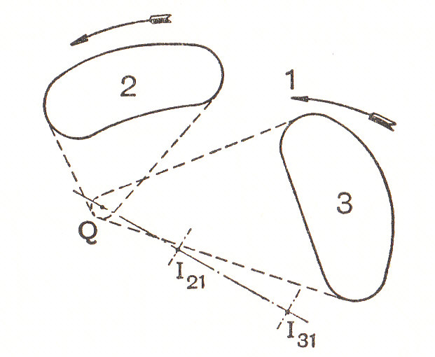
Let the screen represent body 1 and let be the respective instantaneous centres of body 2 relative to body 1 and body three relative to body 2. The instantaneous centre of body 3 relative to body 2 is that point which at a given instant is moving with the same velocity whether considered to be fixed to body 3 or as fixed to body 2. It can be seen that only those points on the bodies 2 and 3 which lie on the line
(produced if necessary)can be moving in the same direction at the given instant. Let Q be a point on the extension of
. Then
is at right angles to
when Q is considered to be a fixed point on body 2. Also
is at right angles to
when Q is considered to be a point on body 3. Then
where are tangular velocities of the bodies 2 and 3 relative to body 1.
If this condition is satisfied, then the point Q coincides with the instantaneous centre of the body 3 relative to body 2.
It should be noticed that for a kinematic chain with l links, the total number of instantaneous centres will be equal to the number of different combinations of links in pairs
Velocity and Acceleration
Apart from the use of Instantaneous Centres, Velocity can also be determined by differentiating the angular or linear displacement of a point. Acceleration can of course be found from the second differentiation.
Angular Displacement, velocity and Acceleration
Let:-
- The line OP in the diagram rotates around O
- Its inclination relative to OX be
radians.
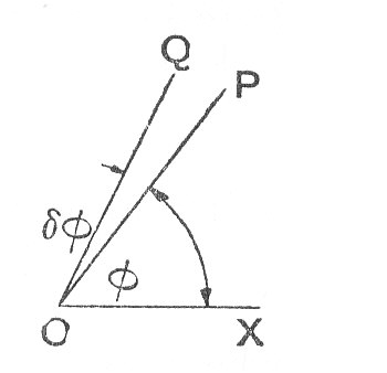
Then if after a short period of time the line has moved to lie along OQ, then the angle is The Angular Displacement of the line.
- Angular Displacement is a vector quantity since it has both magnitude and direction.
Angular Displacement
In order to completely specify and angular displacement by a vector, the vector must fix:-
- The direction of the axis of rotation in space.
- The sense of the angular displacement. i.e. whether clockwise or anti-clockwise.
- The magnitude of the angular displacement.
In order to fix the vector can be drawn at right angles to the plane in which the angular displacement takes place, say along the axis of rotation and its length will be , to a convenient scale, the magnitude of the displacement.
The conventional way of representing the sense of the vector , is to use the right-hand screw rule. i.e,
- The arrow head points along the vector in the same direction as a right handed screw would move, relative to a fixed nut.
- Using the above convention, the angular displacement
shown in the diagram would be represented by a vector perpendicular to the plane of the screen and the arrow head would point away from the screen.
Angular Velocity
- This is defined as the rate of change of angular displacement with respect to time.
- As angular velocity has both magnitude and direction it is avector quantity and may be represented in the same way as angular displacement.
- If the direction of the angular displacement vector is constant. i.e.The plane of the angular displacement does not change its direction,. Then the angular velocity is merely the change in magnitude of the angular displacement with respect to time.
Angular Acceleration
- Defined as the rate of change of angular velocity with respect to time.
- A Vector quantity.
- The direction of the acceleration vector is not necessarily the same as the displacement and velocity vectors.
Assume that a given instant a disc is spinning with an angular velocity of in a plane at right angles to the screen and that after a short interval of
its speed has increased to
.
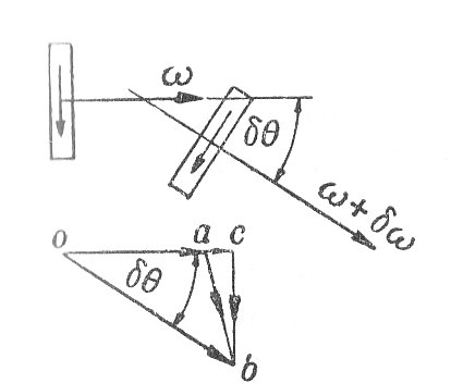
Then applying the right-hand rule:-
- The angular velocities at the two instants are represented by the vectors oa and ob
- The change of angular velocity in a time of
is represented by the vector ab. This can be resolved into two components ac and cb which are respectively parallel and perpendicular to oa
Hence.
- The component parallel to oa is given by:-
- The component perpendicular to oa is given by
Note
is the rate of change of direction of the vector oa
is the rate of change of the magnitude of the velocity ω of the disc.
is the rate at which the direction of
and therefore the plane of the rotation of the disc is changing.
- The total angular acceleration of the disc is the vector sum of
Two particular cases should be noted:-
- If the plane of rotation of the disc is constant in direction, then
is zero and the component of acceleration
- If the angular acceleration of the disc is constant in magnitude but the plane of rotation changes direction at the rate
- The direction of this acceleration vector is at right angles to the angular velocity vector and lies in the plane of motion of the velocity vector.
Precessional Motion and Gyroscopic Acceleration.
- The change in direction of the plane of rotation of the disc is known as Precessional motion and
- The angular acceleration
Forces in Mechanisms.
The forces acting on the individual links of a mechanism can be analysed using the laws of Statics. Inertia forced must either be neglected or allowed for by using the methods shown under Inertia Forces and Couples. Each link is in equilibrium under the action of the external forces acting on it and the reactions at points of contact with other links. The following principles apply:-
- Action and reaction between two bodies must be equal and opposite.
- If a body is acted upon by forces at two points only then these forces must be not only equal and opposite but in the same line. e.g. the reactions at each end of a link connected by single pin joints to adjoining links and not acted upon by any external forces must be equal and in the direction of the line between the pin joints.
- If a body is acted upon by three forces only then these must pass through a common point
- In general for a body in plane motion, three conditions oe equilibtium cna be obtained by resolving and or taking moments.
Note. If only the input and output forces on a mechanism are required it is often possible to use the principals of work (or power) to give results directly without considering intermediate forces.
Friction
Smooth surfaces are defined by the properties that when they are in contact, the surfaces is always perpendicular to their common tangent plane. It can, however, be verified experimentally that no surfaces are perfectly smooth and that whenever there is a tendency for two bodies which are in contact to move relative to each other, a force known as the force of friction tends to prevent the relative motion. The mathematical discussion of the force of friction depends on certain assumptions which are embodied in the so called laws of friction and are found to be in close agreement with experiments.
- Law 1 When two bodies are in contact the direction of the forces of Friction on one of them at it's point of contact, is opposite to the the direction in which the point of contact tends to move relative to the other.
- Law 2 If the bodies are in equilibrium, the force of Friction is just sufficient to prevent friction and may therefore be determined by applying the conditions of equilibrium of all the forces acting on the body.
The amount of Friction that can be exerted between two surfaces is limited and if the forces acting on the body are made sufficiently great, motion will occur. Hence, we define limiting friction as the friction which is exerted when equilibrium is on the point of being broken by one body sliding on another. The magnitude of limiting friction is given by the following three laws.
- Law 3 The ratio of the limiting friction to the Normal reaction between two surfaces depends on the substances of which the surfaces are composed and not on the magnitude of the Normal reaction. This ratio is usually denoted by
Thus if the Normal reaction is R, the limiting friction is
For given materials polished to the same standard μ is found to be constant and independent of R.
- Law 4 The amount of limiting friction is independent of the area of contact between the two surfaces and of the shape of the surfaces, provided that the Normal reaction is unaltered.
- Law 5 When motion takes place the direction of friction is opposite to the direction of relative motion and independent of velocity. The magnitude of the force of friction is in a constant ratio to the Normal reaction but this ratio may be slightly less than when the body is just on the point of moving.
It should be stressed that the above laws are experimental and are accepted as the basis for the mathematical treatment of friction. Modern theory suggests that the force of friction is in fact due to the non - rigidity of bodies. When one body rests on another, there is always an area of contact, which is much smaller than the apparent area and also depends on the the normal pressure between the bodies. Friction is considered to be due to the fusion of materials (of which the bodies are composed) over the area of contact. Therefore friction would be proportional to the area of contact and therefore proportional to the normal pressure as assumed in the above laws.
Angle of Friction
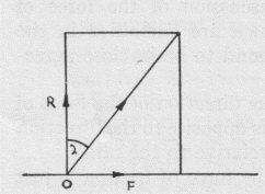
Let R be the normal reaction at a point of contact O and F the frictional force acting in a direction perpendicular to R. Then the total force at O is given by (1)
acting in a direction making an angle (2)
with the normal reaction.
If friction is limiting, F;=;μ:R and the action at O makes an angle of tan^{-1} μ with the normal reaction. This angle is denoted by λ.
Thus (3)
and the magnitude of the limiting friction can be found if either μ or λ is known.
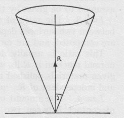
If the direction in which the body tends to move is varied the the force of limiting friction will always lie in the plane through O perpendicular to the normal reaction and the direction of the total action at O will always lie 0n a cone with it's vertex at O and axis along the line of the normal reaction. The semi vertical angle will be λ
This cone is called the cone of friction.
The Friction Circle and Friction Axis
For a turning pair ( Shaft and Journal or Pin and Bearing0 it is assumed that contact is along the axial line and that the total reaction will pass through the position of contact. Diagram (a) shows the forces when the shaft is at rest.
It is assumed that there is no friction and the only two forces are P and the reaction R. When movement occurs, the Total Reaction must be inclined at the Friction angle and this can only be achieved if the Point of Contact moves to a position as shown in Diagram (b). As Friction must oppose movement the Point of Contact will move around the Pin against the Direction of Motion. The Total Reaction will always be Tangential to a Circle centre O and radius . This is known as The Friction Circle
Where a Link joins two turning pairs, the line of thrust or Tension in the Link must be Tangential to the Friction Circles at its ends. This line is called The Friction Axis
Worked Examples
The workings of associated with the following examples , have been hidden. To view them please click on the red button.
Example 1
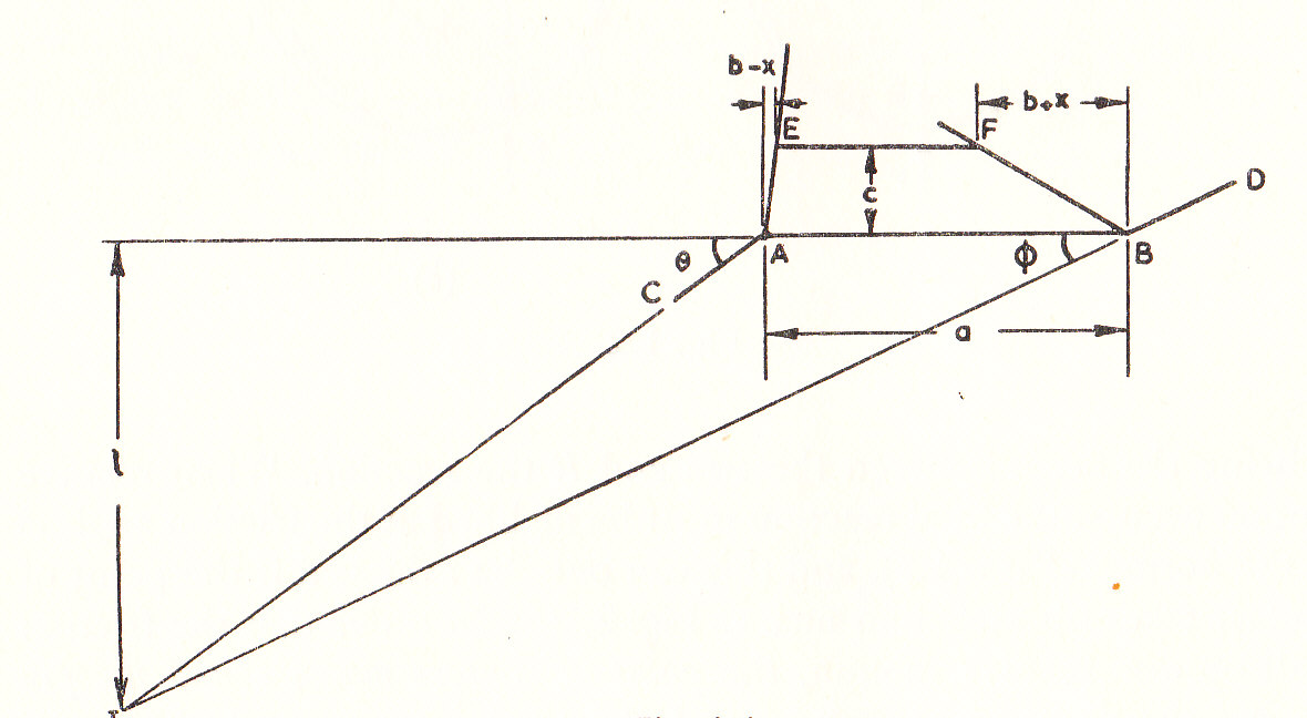
In the Davies Steering gear shown, the stub Axles CA and DB are pivoted at A and B on the rigid axle and are continuous with the arms AG and BH respectively. The cross link EF is pivoted at the ends to the blocks sliding on the arms AG and BH and slides in the guides at M and N.
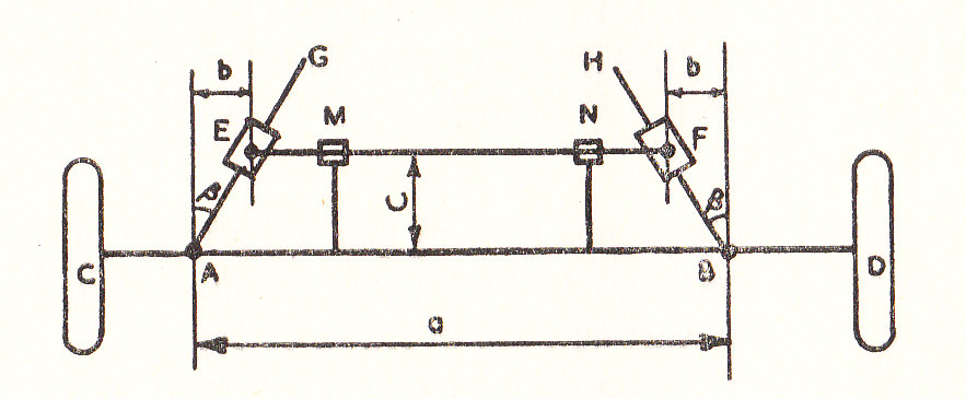
Show that correct steering is obtained if the distance between the front and rear axles is (U.L.)
Example 2
A linkwork for operating the drum of an engine indicator is shown in the Drawing. A pin B projects from the cross-head and works in the slot at the end of a lever oscillating about a fixed pin at A. The Cord which rotates the drum is attached at C to the rim of a sector which is fixed to the lever.
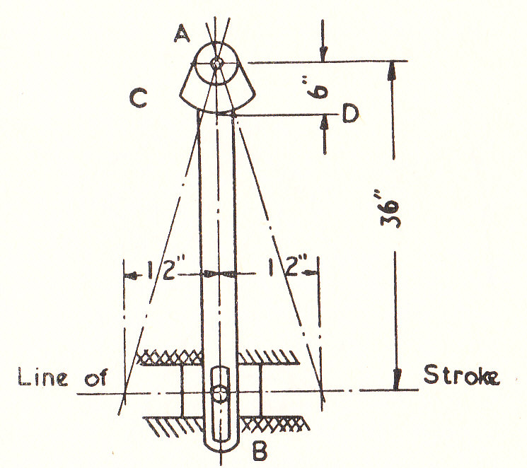
It is intended that when the cross-head has moved 1/n of its half-stroke from the central position, a point D on the cord should also be displaced by 1/n of its half stroke.
When the cross-head is at quarter-stroke, find the distance of D from its position of one-quarter of its stroke and express this distance as a percentage of the whole stroke.
For what value of n is the error a maximum? (U.L.)
Example 3
The figure shows a Geneva-stop motion used to drive a cinematograph film. Shaft A rotates at constant speed and carries a pin P which engages in turn with each of the four slots in the plate attached to B. B is therefore stationary for 3/4 of a revolution of A and turns 1/4 of a revolution to advance the film during the remaining 1/4 revolution of A.
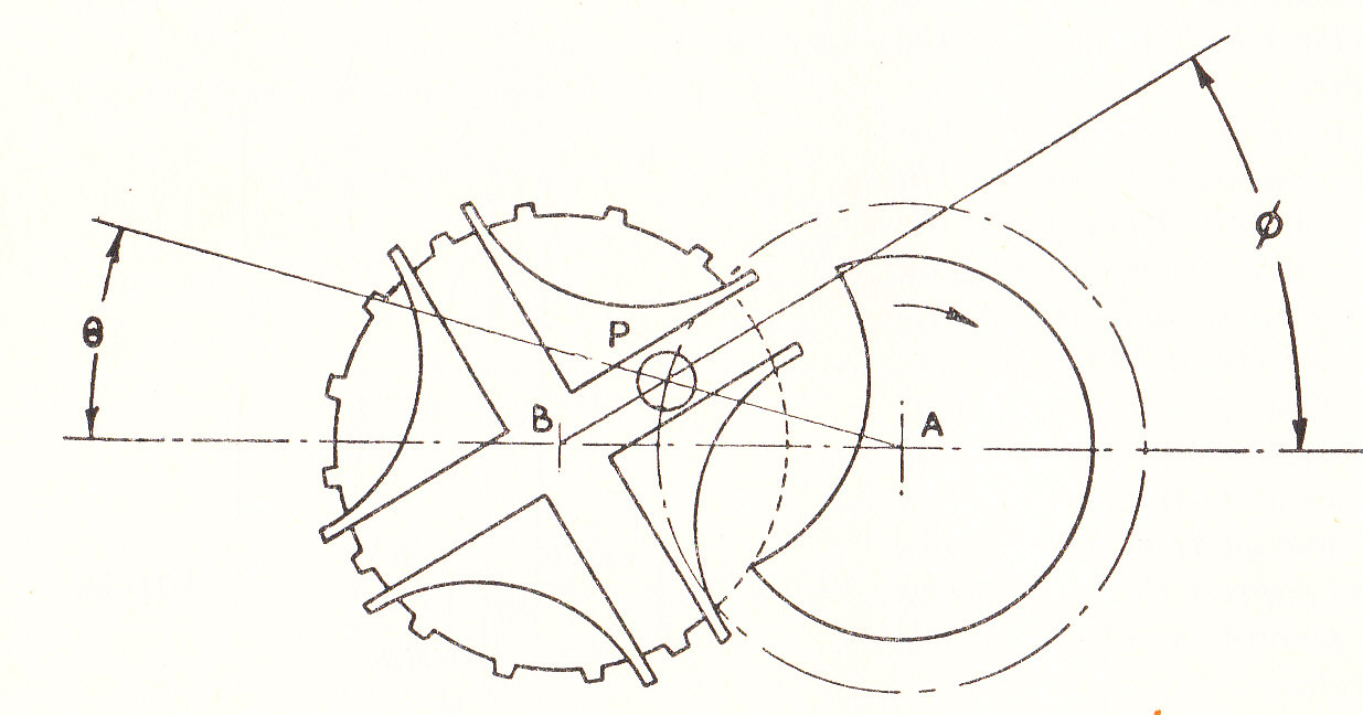
The centre distance the pin path radius AP. If during a period of contact
are the angular displacements of the shafts, show that
and determine the angular velocity of B in terms of
Hooke's Universal Coupling
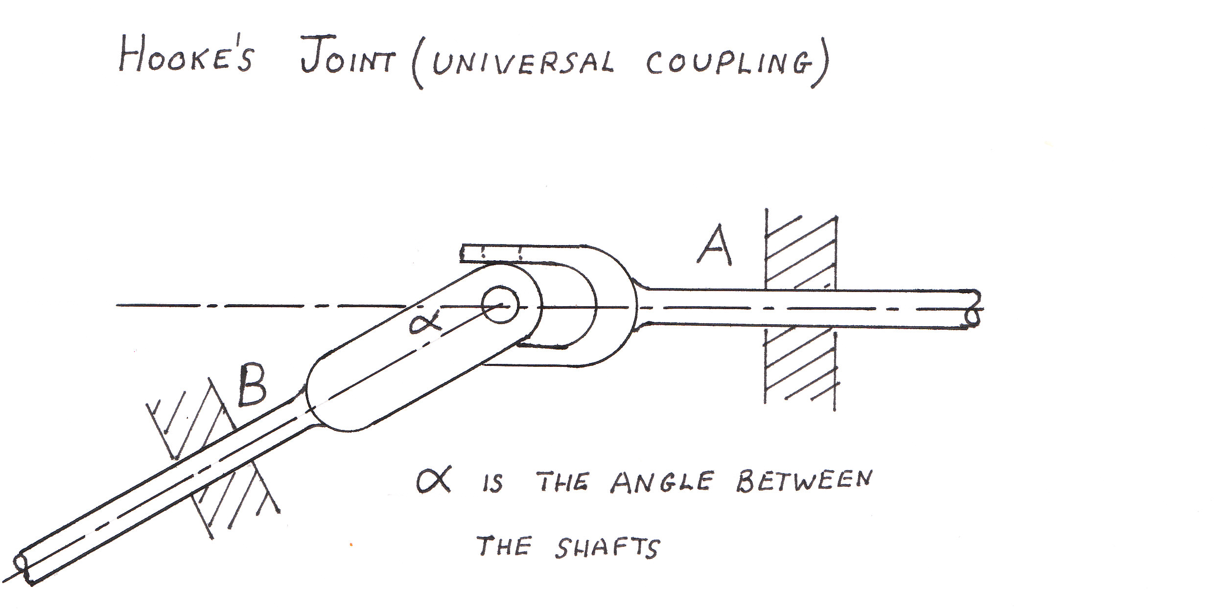
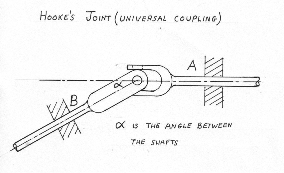
The diagrams show a Hook's joint in which shaft A drives shaft B through an angle of]
Starting position
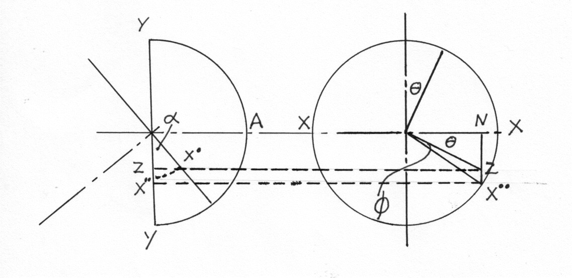
The cross arms YY and XX are in a plane perpendicular to A. Now turn through an angle theta Project OX onto the original plane at Z. Note angle ZOY is always a right angle
Rotate the plane of OX{'} about OX. bring
Example 4
If the angle of divergence of a Hooke's joint is 27 1/2 degrees and a steady torque of 220 lb.ft. is applied to the driving shaft whilst it is rotating at 120r.p.m., what must be the weight of the flywheel (radius of gyration 9 in.) attached to the driven shaft, if the output torque does not vary by more than plus or minus 25%
The value of for maximum acceleration of the driven shaft may be taken from:-
using equation (9)
Permissible acceleration torque (Pt) equals the transmitted minus the output torques
From equation (10)
Double Hooke's Joint
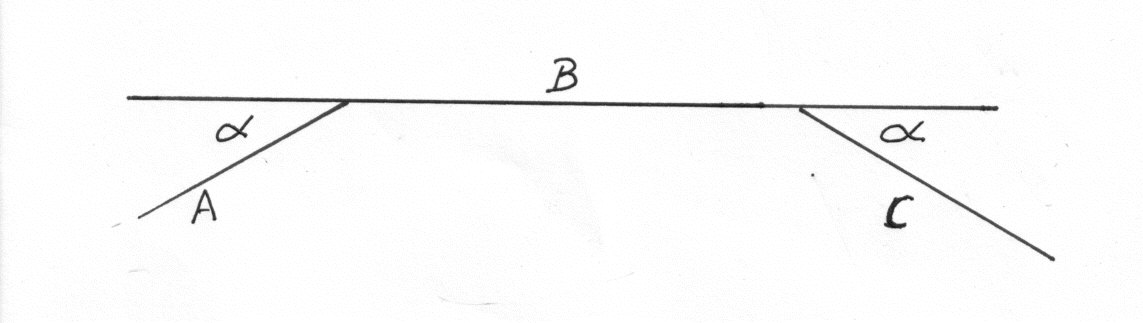
i.e. the shaft angle A to C is two alpha and the intermediate shaft B makes an angle alpha with both A and C NOTE THE CROSS ARMS ATTACHED TO A AND C MUST BE IN THE SAME PLANE.
Example 5
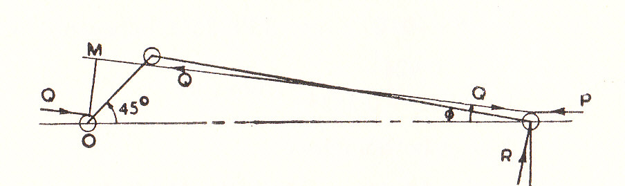
In a direct acting steam engine the stroke is 2 ft. and the diameter of the piston is 1 ft.. The length of the connecting-rod is four times the length of the crank. The diameters of the crosshead pin, crank pin and crankshaft are 3.5, 4.5, and 5.0 inches respectively. The coefficient of friction between the crosshead guide is 0.08 and for the two pins and crankshaft is 0.055. When the crank has moved through an angle of 45^{0} from the inner dead centre the effective steam pressure on the piston is 100 lb./sq.in.
Draw a diagram to show the direction of the forces acting in the linkwork and calculate the turning moment on the crankshaft. (U.L.)
Example 6
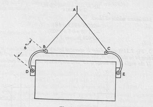
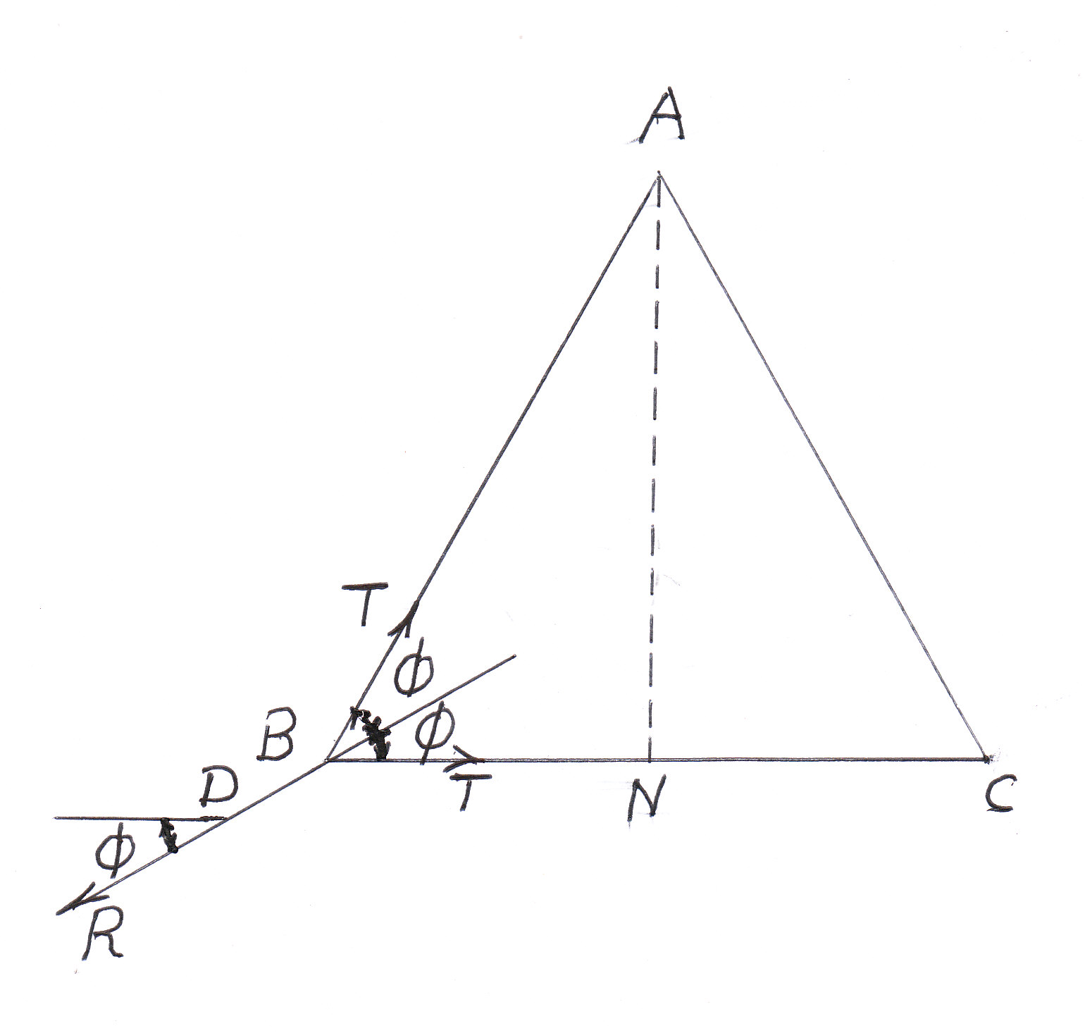
The diagram shows a method of lifting stone blocks. The chain ABC passes over pulleys at B and C to which the links B D and CE are pivoted. These carry pads which press against the stone block. If the coefficient of friction between the block and the pads is 0.4 and the length of the chain is 5 ft. , find the smallest blocks which can be lifted. Neglect friction at the pins and assume the pulleys at B and c to be OF negligible diameter.
Example 7
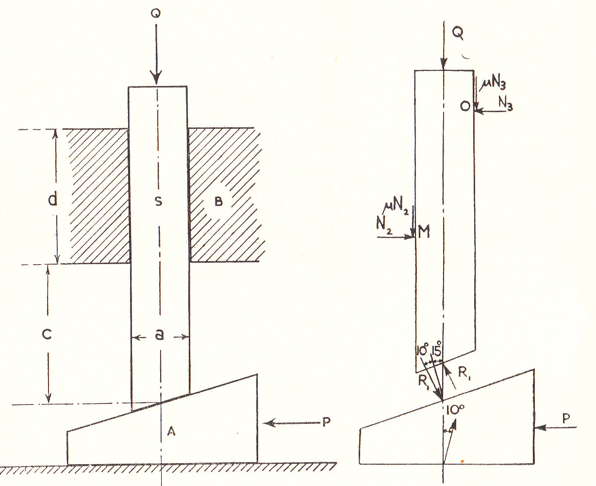
The figure shows a slider S operated by a wedge A. The slider is an easy sliding fit in the guide B. The distances c and d are equal and a is 0.4 c.
If the angle of the wedge is and the angle of friction at all surfaces is
find the resistance Q
which can be overcome by the slider in terms of the effort P applied to the wedge
Example 8
The following diagram shows a friction drive between a driving shaft A and a driven shaft B, whose axes intersect at right angles. The cylinder C, integral with shaft A has a radius of 1.25 ins.and presses against disc D which is keyed to shaft B
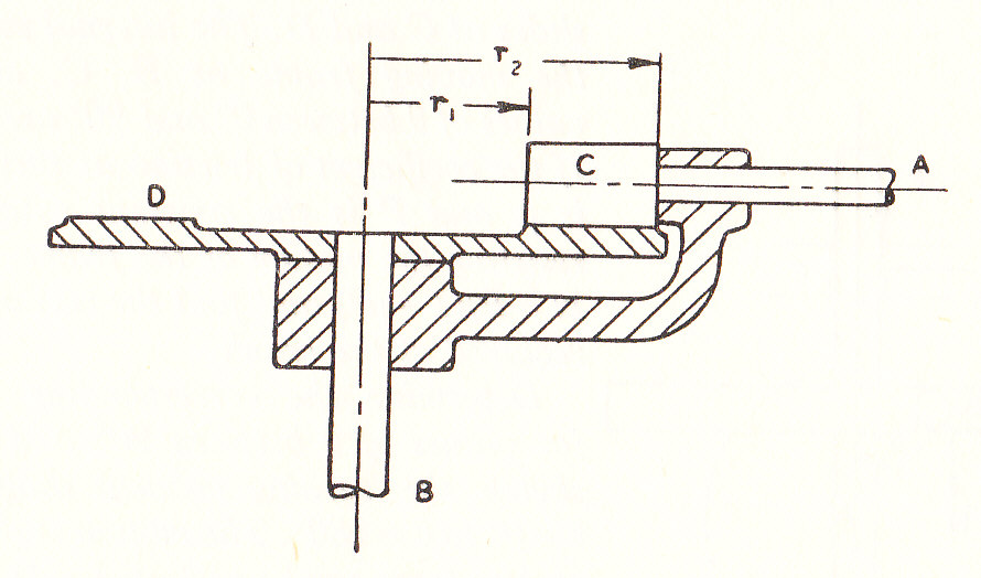
The friction of the disc has an outer radius
and an inner radius
. The total vertical force between C and D is 60 lbs., the pressure along the line of contact being uniform. Friction on the thrust bearing underneath D may be neglected.
a) Find the velocity ratio between A and B when there is no resisting torque on B
b) Find the coefficient of friction between C and D if a torque of 2.25 lb.in. is required on A to drive the mechanism when there is no resistive torque on B
Example 9
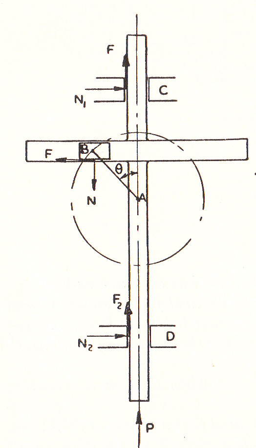
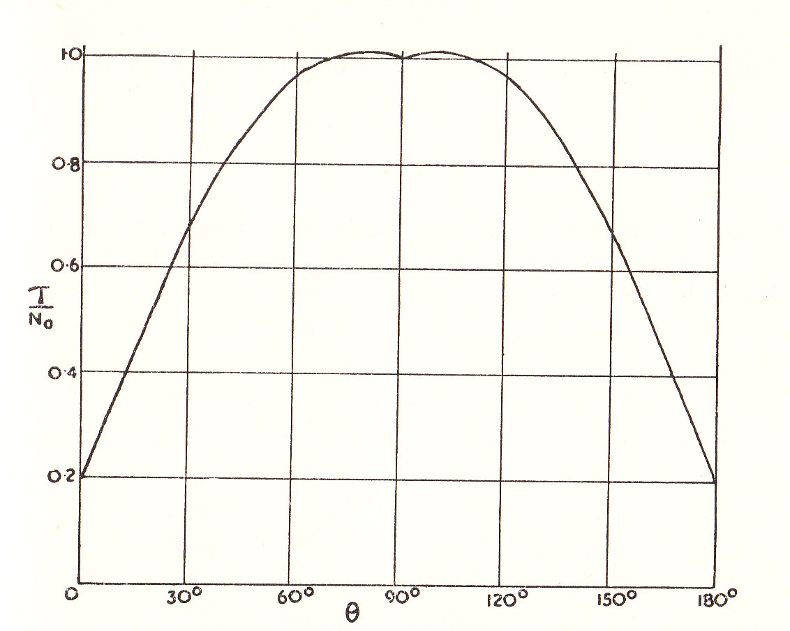
In the mechanism shown in the diagram, the crank AB of length a, rotates about a fixed centre A, to produce a reciprocating motion of the frame which is supported in slides at C and D. The internal reactions of the moving frame at B, C, and D, for values of between
are as shown. If the coefficient of friction at these contacts is
and P is the constant external force resisting the motion of the frame, show that:-
and find the Turning Moment required at the crank.
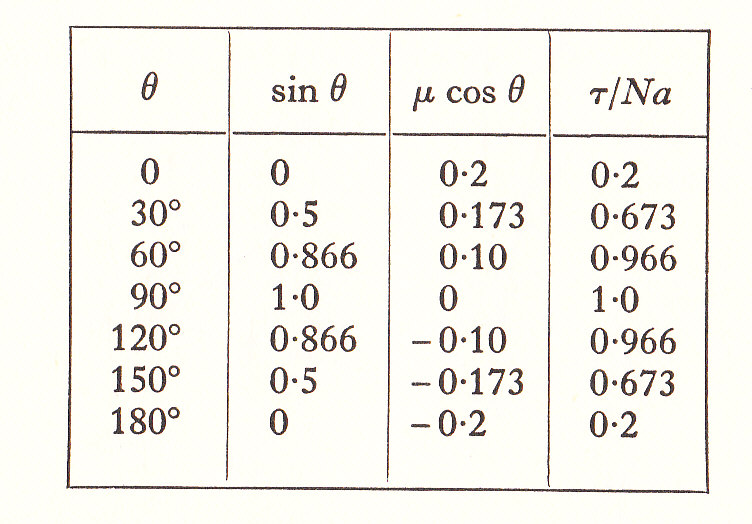
Determine the corresponding expression for values of between
and sketch the Turning Moment diagram from
. As the motion is slow, Inertia forces can be neglected.
Example 10
The figure shows diagrammatically the Toggle mechanism of a Press. The driving Pinion A turns at 120 r.p.m. and the Crank OC is 4 inches long. Find the angular velocity of each of the links for the given position of OC. The Gear ratio between the Driving Pinion and the wheel is 4.5.
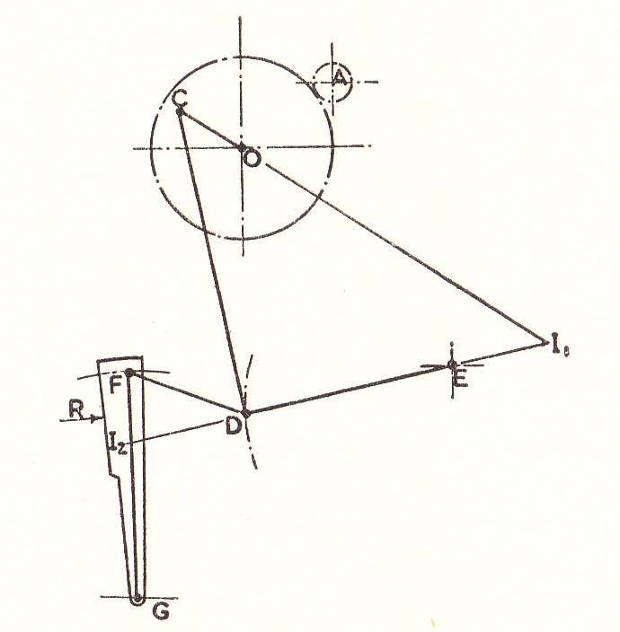
If a Torque of 30 lb.ft. is applied to the driving pinion A and the effects of friction and Inertia are neglected, what is the magnitude of the force R which can be overcome?