Cams
Cams; their profiles and the velocity and acceleration of their associated followers
You're viewing an older version of this page (#3542). View the current version.
Introduction
Cams come in all shapes and sizes and are found in most branches of engineering. Indeed without them many of our everyday appliances would not work. Simple cams form the basis of rotary cam timers which are used to control some household appliances , car engine would not work without the cams and many industrial machine tools rely upon them. In truth cams are ubiquitous.
Types of cams
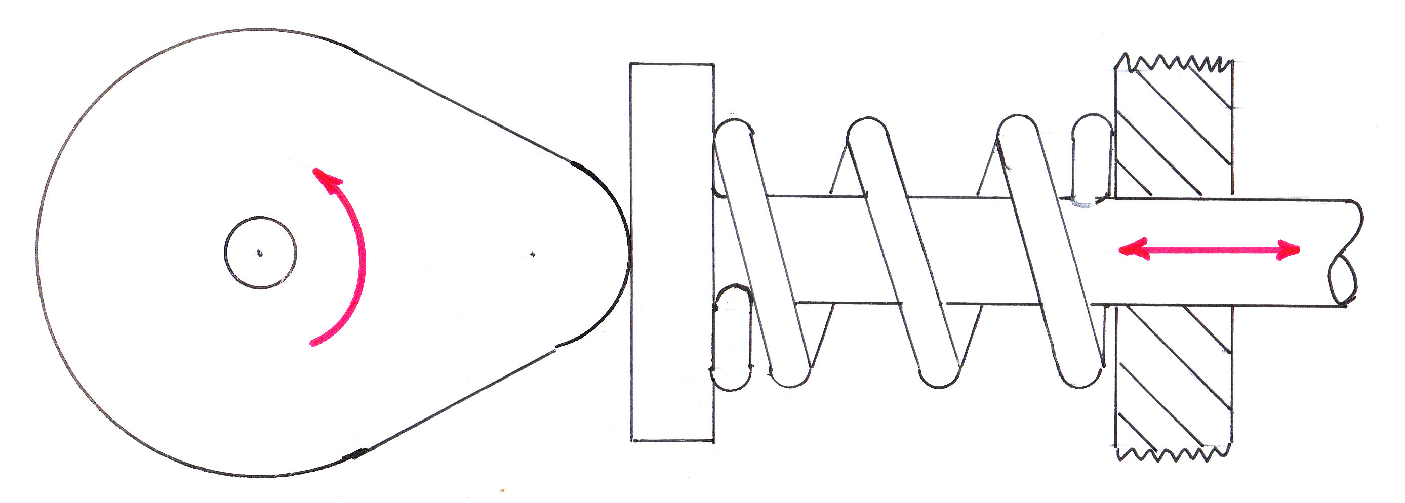
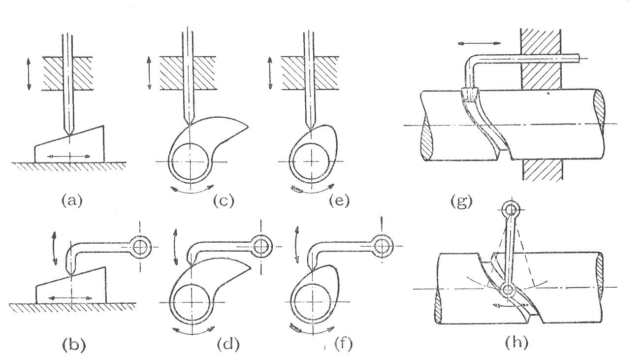
A {Cam} is a reciprocating, oscillating or rotating body which imparts reciprocating or oscillating motion to a second body, called the follower, with which it is in contact. The shape of the cam depends upon its own motion, the required motion of the follower and the shape of the contact face of the follower. Of the many types of cam, a few of the most common are shown in the diagram.
In general the motion of the follower is only determined positively by the cam during a part of each stroke whilst during the remainder of the stroke contact between the cam and the follower has to be maintained by an external force, often supplied by a spring. In this connection it should be noticed that the cam does not, as would at first appear likely, to determine the motion of the follower during the whole of the its out-stroke. Actually , owing to the inertia of the follower, it is only during the first part of the out-stroke and the latter part of the return that the motion of the follower is positively controlled by the cam.
Cams are classified according to the direction of displacement of the follower with respect to the axis or oscillation of the cam. The two most important types are :-
- Disc or Radial Cams In these the working surface of the cam is shaped that the reciprocation or oscillation of the follower is in a plane at right angles to the axis of the cam. ( see examples c; d; e; f above )
- Cylindrical Cams These are often used in machine- tools and the cam imparts an oscillation or reciprocation to the follower in a plane parallel to the axis of the cam. ( see examples g and h above)
Types of Follower.
Followers can be divided according to the shape of that part which is in contact with the cam.. The following diagram shows some of the more common types:-
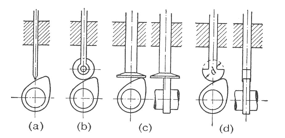
- Knife edged (a) These are not often used due to the rapid rate of wear of the knife edge. Tis design produces a considerable side thrust between the follower and the guide.
- Roller Follower (b) The roller follower has the advantage that the sliding motion between cam and follower is largely replaced by a rolling motion. Note that sliding is not entirely eliminated since the inertia of the roller prevents it from responding instantaneously to the change of angular velocity required by the varying peripheral speed of the cam. This type of follower also produces a considerable side thrust.
- Flat of Mushroom Follower (c) These have the advantage that the only side thrust is that due to friction between the contact surfaces of can and follower. The relative motion is one of sliding but it may be possible to reduce this by off setting the axis of the follower as shown in the diagram. This results in the the follower revolving under the influence of the cam.
- Flat faced Follower These are really an example of the mushroom follower and are used where space is limited. The most obvious example being automobile engines.
Limits imposed on the shape of the cam working surface by the choice of follower type.
- The knife follower does not, theoretically, impose any limit on the shape of the cam.
- The roller follower demands that any concave portion of the working surface must have a radius at least equal to the radius of the roller.
- The flat follower requires that everywhere the surface of the cam is convex.
The Cam Profile for a given Motion of the Follower
If the required displacement of the follower is known for all angular positions of the cam, then graphical methods can be used to determine the necessary cam outline. The method of work is as follows:-
- Select the minimum cam radius i.e. zero displacement of the follower.
- Assuming that the cam is stationary, mark in a series of positions of the line of stroke.
- From a knowledge of the displacements in each of these positions and allowing for the type of follower to be used, it is possible to draw the required profile of the cam. ( See Examples (2) and (3))
Two particular motions of the follower are frequently specified. These are:-
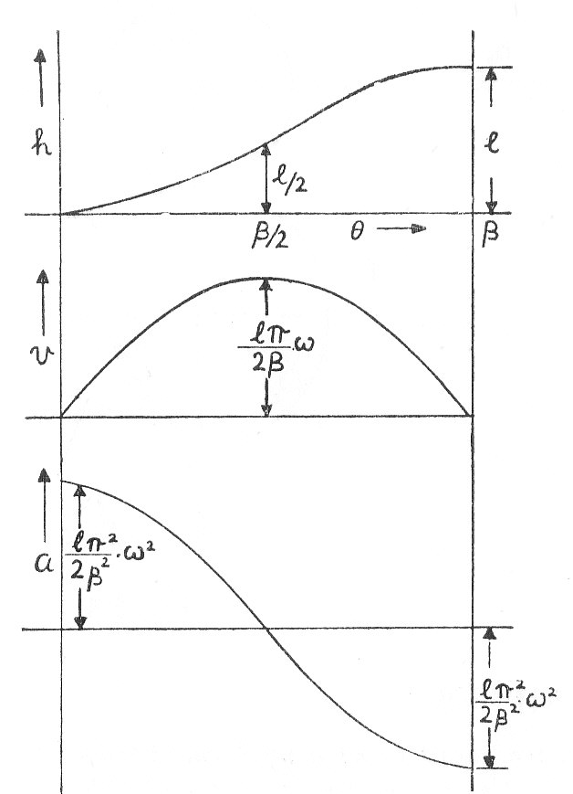
a) Simple Harmonic Motion
If is the follower lift which is to take place during a cam rotation of
, then the displacement at any cam angle
is given by:-
Differentiating with respect to time
From which the maximum velocity is given by:-
Differentiating equation (2) w.r.t.t.
The following graph shows the displacement velocity and acceleration of the follower over one revolution of the cam.
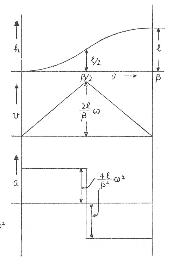
b) Uniform acceleration and retardation If these are also made equal, the result is to keep the inertia forces to a minimum for a given lift in a given time.
If a is the uniform acceleration then:-
If the acceleration and retardation are numerically equal and if is the angle of lift. Then when
The Motion of the Follower fro a given Cam Profile
The motion imparted to the follower by a given cam profile may be determined graphically using the reverse process that was described in the last paragraph. (see Example 1)
Certain standard shapes of cams which are made up of circular arcs and straight lines may be dealt with analytically. This is done by obtaining expressions for the displacement in terms of the cam angle and differentiating for the velocity and acceleration. ( see Examples 6 and 7)
The equivalent Mechanism for a Cam and Follower
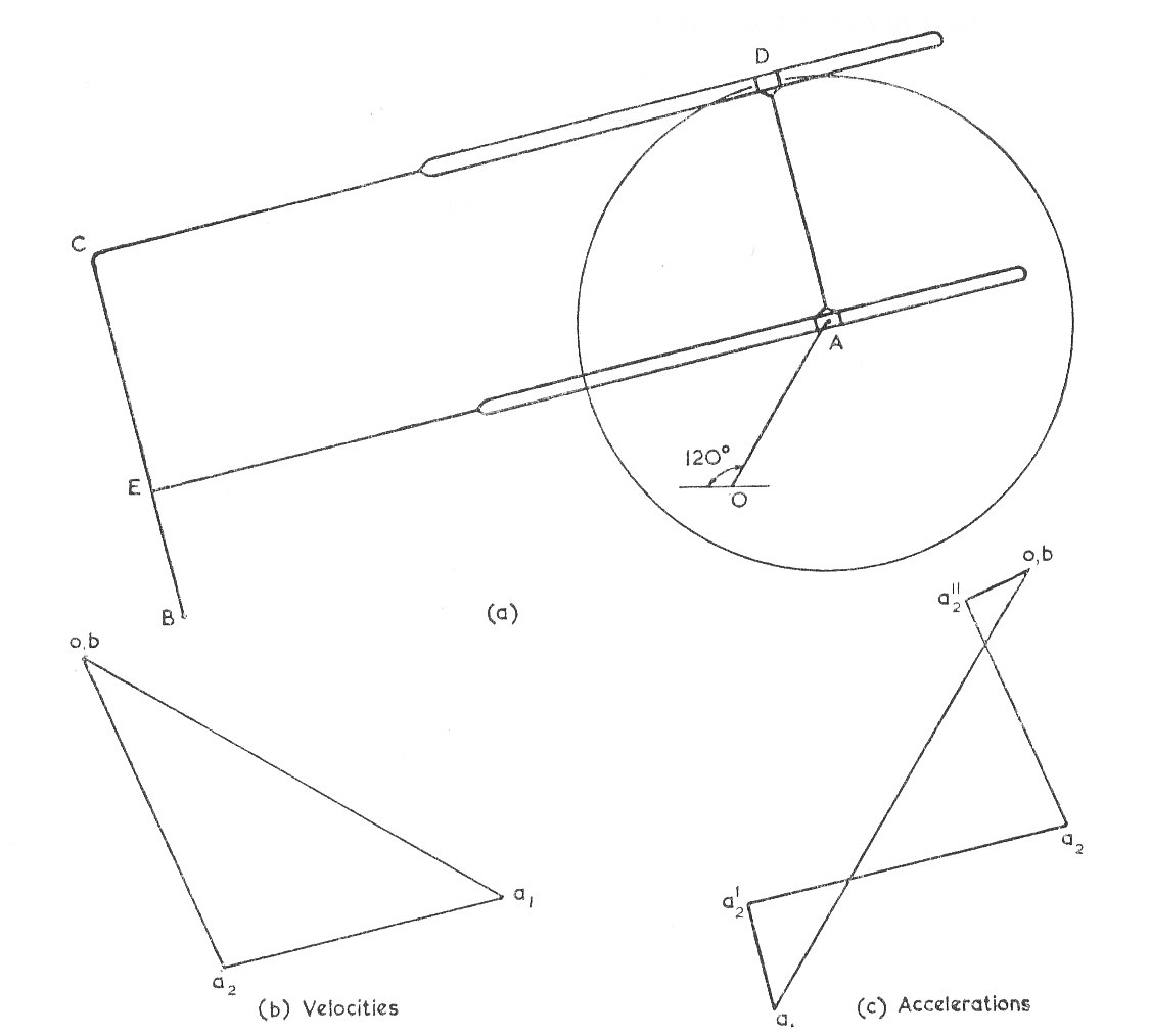
In many cases an equivalent mechanism using lower pairs can be substituted for a given cam and follower, possibly only over a limited range of stroke. If this is done the method of determining the velocity and acceleration which has been described in " Theory of machines, Velocity and acceleration" can be used. A Cam whose profile is made up of circular arcs and tangents is usually amenable to this treatment. The resulting mechanism varies with the type of follower.
When a roller follower is used, a constant distance is maintained between the centre of the roller and the centre of curvature of the cam profile. This can be replaced by a rigid link. Ifg the follower reciprocates as in Examples 5 and 6 the an equivalent slider crank chain is produced. If the follower oscillates as in the following diagram,
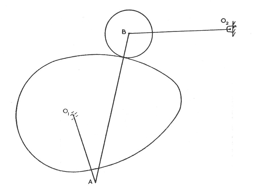
then the motion is equivalent to a four bar chain connecting the centres of cam axis, profile curvature, roller, and follower axis.
A flat footed oscillating follower can usually be replaced by a slotted lever ( See Example 4)
Worked Examples
The workings associated with the following examples have been hidden. They can be seen by clicking on the red button.
Example 1
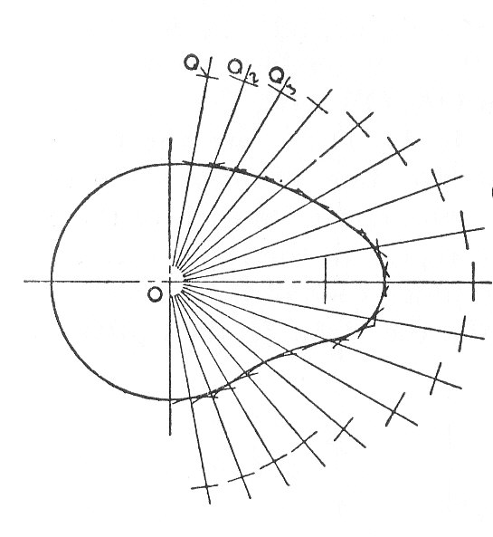
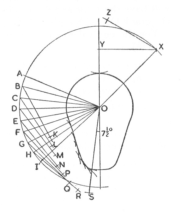
The Cam shown in the diagram rotates about O at a uniform speed of 500 r.p.m. and operates a follower attached to a roller of centre A. The path of Q is a straight line passing through O.
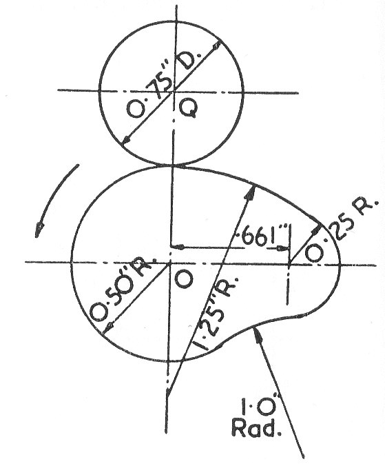
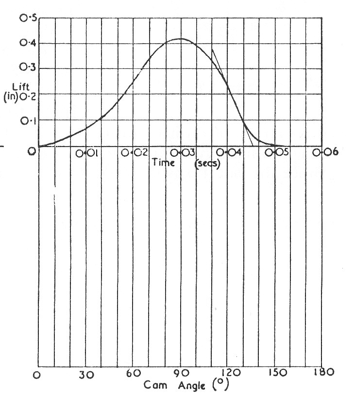
Draw the time lift diagram for the roller centre Q on a base of 1 inch to 0,01 seconds and to a vertical scale four times full size, for a movement of
from the position shown; determine the maximum velocity of the roller centre Q and the cam angle at which it occurs. (U.L.)
Example 2
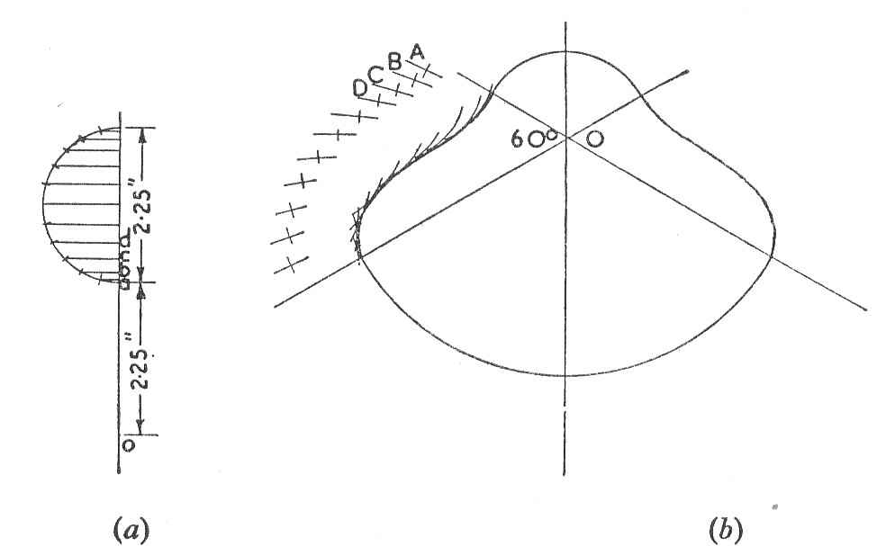
The diagram shows a cam which is used to raise and lower the head of a loom. The line of stroke of the follower passes through the centre of the camshaft and the lift is 2.25 in.The follower dwells for a third of a revolution at the top and bottom of the stroke and the rise and fall each occupy a sixth of a revolution. The minimum cam radius is 1.25 in. and the roller on the follower is 2 in. in diameter. Complete the profile to give harmonic motion during rise and fall. Scale half full size.
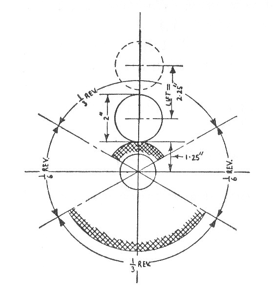
If the shaft rotates at 30 r.p.m. determine the maximum velocity and the maximum acceleration of the follower.
Example 3
A cam turns at a uniform speed of 180 r.p.m. and gives an oscillating follower, 2.5 in. long, an angular displacement of on each stroke. The follower is fitted with a roller 2 in. in diameter, which makes contact with the profile of the cam. The outward and return displacements each take place with uniform acceleration and retardation whilst the cam turns through
and there is a period of dwell in the outward position whilst the cam turns through
.
If the axis of the follower is 3.5 in. from the axis of the cam and the least distance of the roller axis from the cam is 2.5 in., draw the outline of the cam.
Find the maximum angular velocity and the maximum angular acceleration of the follower.
Example 4
A circular cam of 4 in. diameter and an eccentricity of 1.5 in. rotates about a centre O as shown in the diagram.
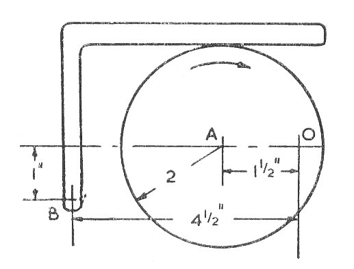
The cam rotates at 100 r.p.m. in a clockwise direction and operates a lever follower pivoted at B. When the cam has rotated by from the position shown, find the angular velocity and acceleration of the follower. (U.L.)
Example 5
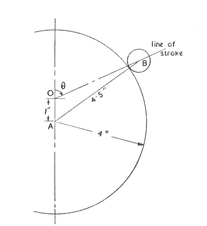
A cam is to cause a slider weighing 1.5 lbs. to move 2 in. in sec. from rest to rest. Compare the maximum velocity reached and the maximum force required if:-
- The slider is given simple harmonic motion.
- The slider is uniformly accelerated and then uniformly retarded.
- The motion is produced by half a revolution of a circular disc of 4 in. diameter and 1 in. eccentricity, the slider ends in a roller of 1 in. diameter and the line of stroke passes through the axis of the cam. (U.L.)
Example 6
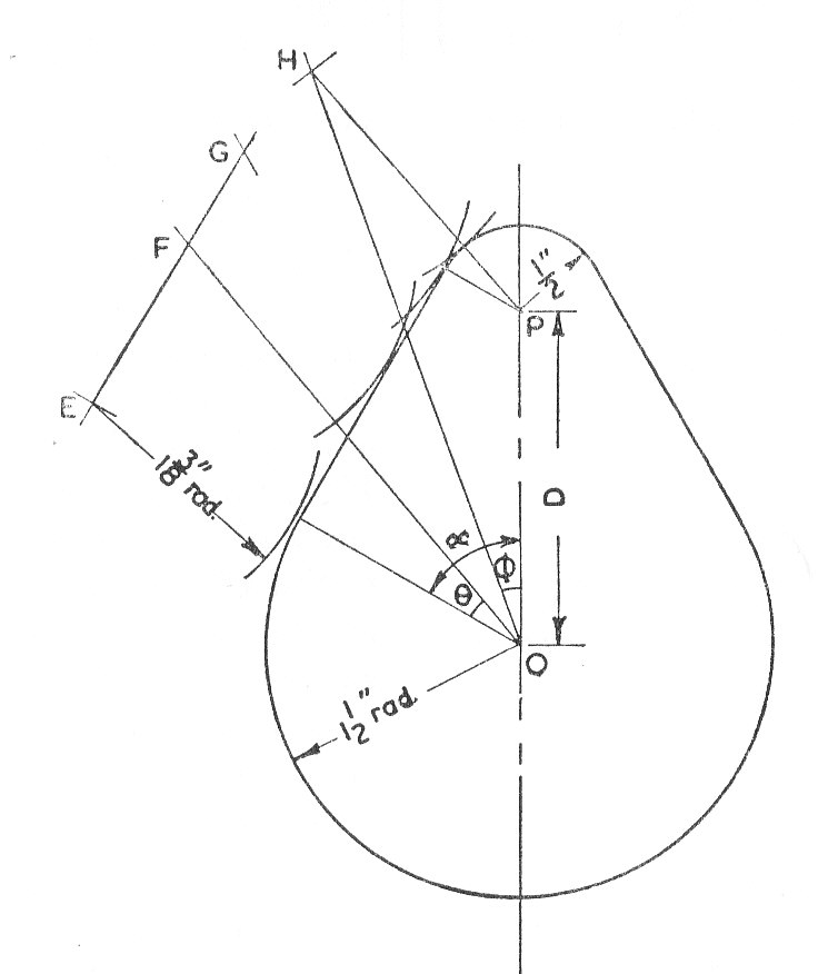
The Follower of a Tangent cam is operated through a roller 2.75.in. in diameter and its line of stroke intersects the axis of rotation of the cam. The cam profile consists of two circular arcs of radii 1.5 in. and 0.5 in. joined by straight lines so as to give the follower a lift of 7/8 in.
If the speed of rotation of the cam is 750 r.p.m., find (a) the maximum velocity of the follower and (b) The acceleration of the follower at the instant that the cam has turned through an angle of from the beginning of the lift.
Example 7
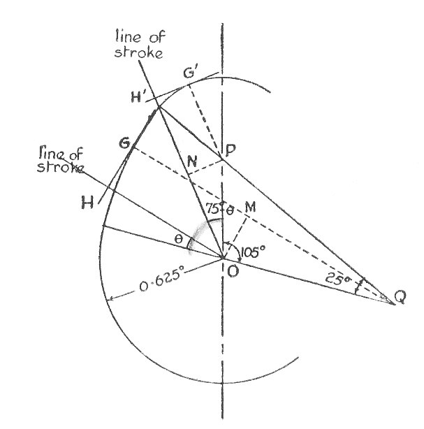
A flat ended valve tappet is operated by a symmetrical cam with circular arcs for flank and nose profiles. The straight line path of the tappet passes through the cam axis. The total angle of action is , the lift is 0.25 in., the base circle diameter is 1.25 in. and the period of acceleration is half that of the deceleration during lift. The cam rotates at 1250 r.p.m.
Determine (a) the nose and flank radii and (b) the maximum acceleration and deceleration whist lifting. (U.L.)
Example 8
A cam of base circle diameter D in. has tangent flanks and operates a follower through a roller of radius R in., the path of the roller centre being a straight line passing through the camshaft axis. The follower acts against a spring of stiffness S lb./in.,and the initial compression is x in. The total effective mass of the follower is M and the spring mass is m.
Obtain an expression for the torque exerted on the camshaft when it is rotating at rads.per sec. and the cam has turned through an angle
from the point at which the roller makes contact with the flank. Neglect the effects of friction. (U.L.)
Example 9
Show that the reaction on a shaft of radius a from a cylindrical bearing in which it rotates with line contact is tangential to a circle of radius called the friction circle, where
is the friction angle at contact.
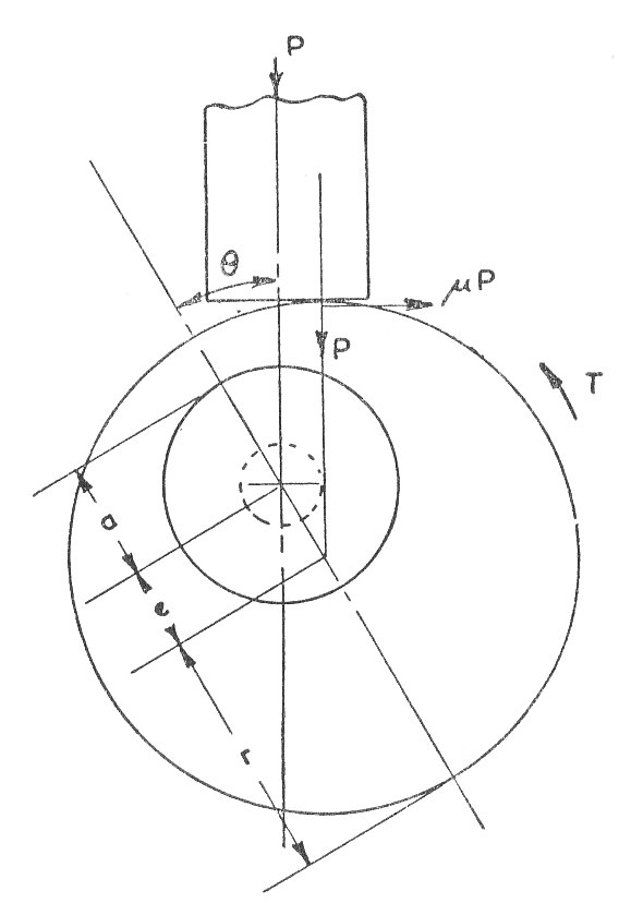
The diagram shows a circular cam of radius r and eccentricity e. The radius of the camshaft is a. It operates a flat ended follower with a straight line passing through thee cam axis. The coefficient of fiction between the can and follower and between the cam and bearings is
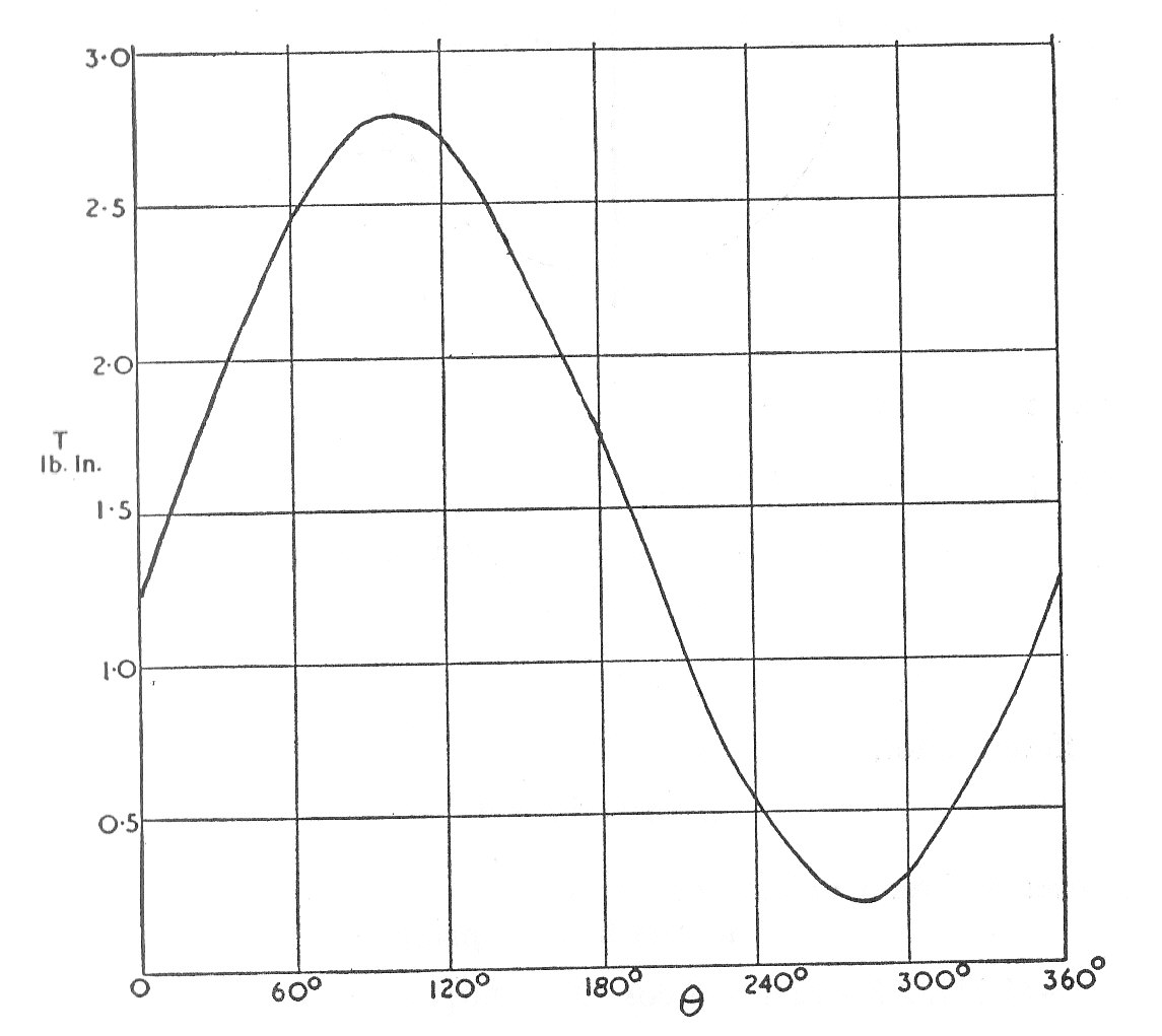
Find an expression for the turning moment T required to rotate the shaft when it has turned an angle from the commencement of lift, the force P on the follower being parallel to the axis and the guide friction neglected.
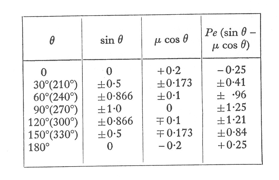
If r = 1 in., a = 0.5 in., e = 0.25 in., = 0.2, and P = 5 lb., sketch the curve showing T over one revolution. (I. Mech. E)
Example 10
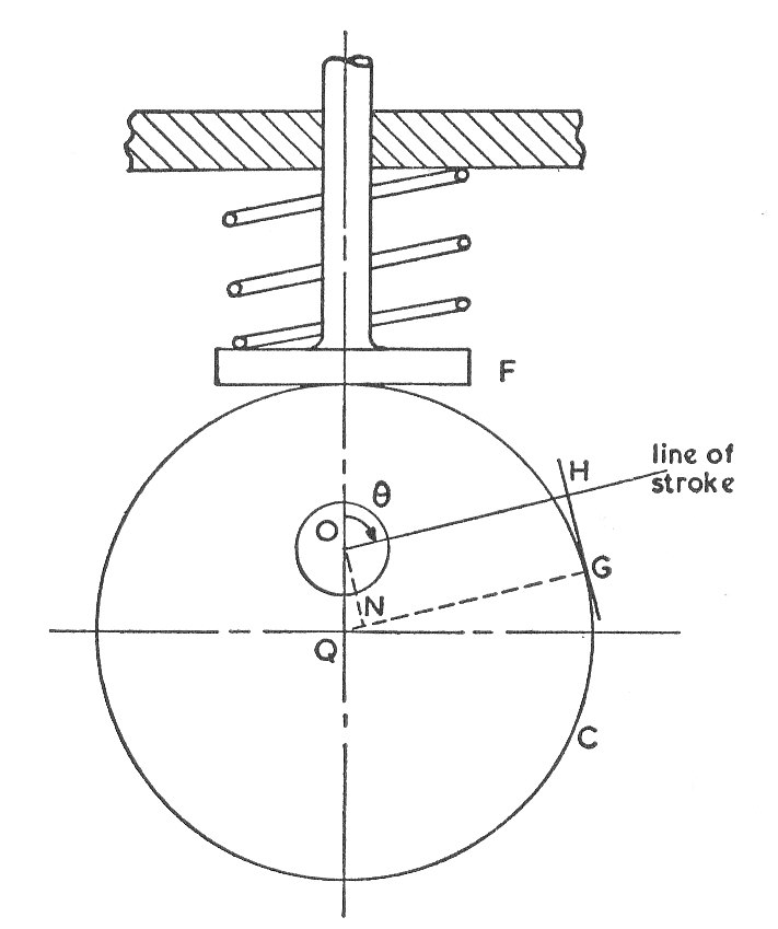
In the mechanism shown in the diagram, a circular cam C of 6 in. diam. and eccentricity OQ of 1.5 in. rotates at a uniform speed about an axis O. A follower F of weight 1.75 lb. is pressed against the cam by a spring of stiffness 60 lb./in.
It is found that at a certain speed the follower ceases to have contact with the cam when the latter has moved through from its lowest position. Find that speed and the maximum height reached by the follower above the axis O. The initial compression of the spring is 1.25 in. The dead weight of the follower and the mass of the spring may be neglected. (U.L.)