The Geometry of Gears
The geometry of both Cycloid and Involute gears. An analysis of the motion between two teeth and the calculation of the path of contact
You're viewing an older version of this page (#3544). View the current version.
Introduction
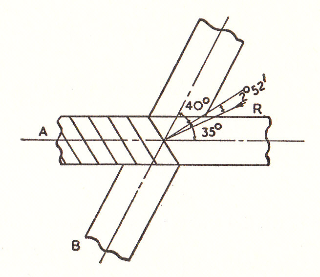
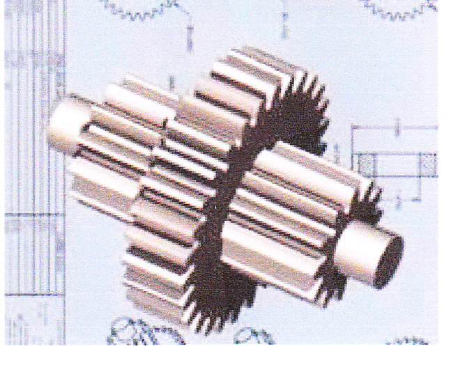
It is difficult to imagine machines which do not include some sort of toothed gear system. These are used for the transmission of motion or of power. The systems include Spur gearingin which the axes of the shafts connected are parallel ( Note Helical Gearing is the name given to a type of spur gearing in which, although the axes of the shafts are parallel, the teeth are cut on helices instead of straight across the wheel parallel to the axes.) Bevel Gearing in which the axes of the shafts intersect and Skew or Spiral Gearing in which the axes are both non parallel and non intersecting.
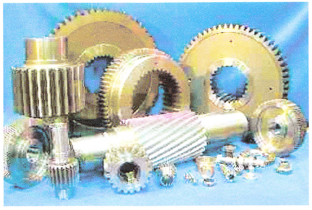
In most forms of toothed gearing the teeth are not theoretically necessary for the transmission of the required motion and a form of friction drive would achieve the required results. However from a practical point of view, the teeth provide in all types of gearing the following:
- A constant velocity ratio between the shafts without any possibility of slippage.
- The ability to transmit large torques from the driving to the driven shaft.
Definitions
Before considering the Theory of gear teeth in detail a few necessary definitions are given. These terms are in general use in connection to toothed gearing.
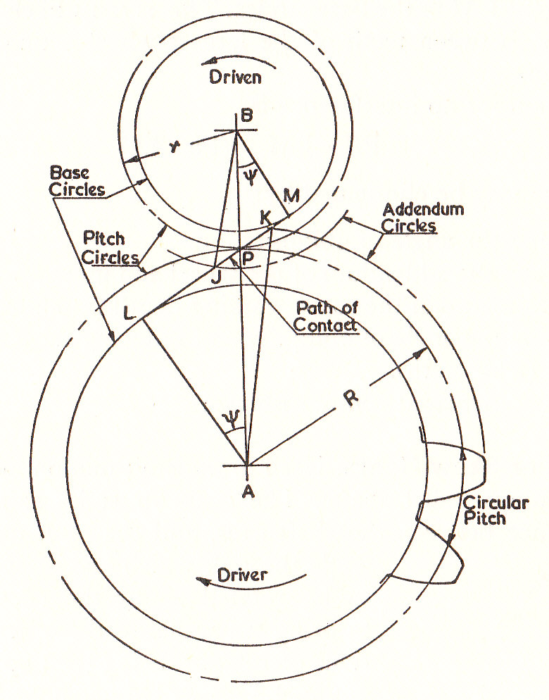
- The Pitch Circle Diameter is the diameter of a circle which by a pure rolling action would transmit the same motion as the actual gear wheel. It should be noted that in the case of wheels which connect non-parallel shafts, the pitch circle diameter is different for each cross section of the wheel normal to the axis of rotation.
- The Pitch Point is the point of contact of two pitch circles.
- The Pitch Line is the line of contact of two Pitch surfaces.
- The Circular Pitch, p is the length of arc round the pitch circle between corresponding points on adjacent teeth.
- The Diametral Pitch, p_d is the number of teeth per unit length of diameter
an it can easily be shown that
- The Module, m
- The Path of Contact (JK on the diagram) is the path traced out by the point of contact between a pair of teeth. This may be divided into "Approach" and "Recess".
- The Arc of Contact is the arc traced out along the pitch circle whilst one pair of teeth is in contact. Again this can be divided into "Approach" and Recess". It can be shown that the arc of contact
since the path of contact represents a distance round the bases circle.
- The Addendum is the radial length of a tooth from the pitch circle to the tip of the tooth. This is normally constant for a set of gears and the standard value is
- The Dedendum is the radial length of a tooth from the pitch circle to the root of the tooth.
- The Pressure Angle or Angle of Obliquity)
is the angle between the common normal (LM) and the tangent at the pitch point P. The normal pressure between teeth acts along LM.
- \b{A Pinion is the smaller of two mating gear wheels.
The Motion Transmitted between two Teeth
The diagram shows two gear wheels with centers at A and B and mating teeth in contact at K . LM is the common Normal at the point of contact and AL and BM are lines through A and B perpendicular to LM . LM cuts AB at P.
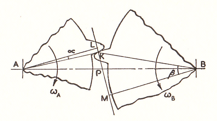
The velocity of the point on A perpendicular to AK. Similarly
on B in a direction perpendicular to BK. The condition for contact between the teeth to be maintained is that the velocity components along the common normal must be the same for each tooth.
or
Thus the condition that there is a constant velocity ratio is that the common normal at the point of contact should pass through a fixed point (The Pitch Point) on the line of centers. The motion then transmitted is equivalent to the pure rolling of two cylinders with centers at A and B and radii AP and BP. It can be shown that it is possible to choose any reasonable shape for the profile of the teeth on one wheel provided that the mating teeth are designed to satisfy the above condition. However for practical reasons, the tooth shape is either Cycloidal orInvolute.
Since the motion is equivalent to pure rolling at P then P must be the instantaneous center of B relative to A and the velocity of sliding between the teeth at K is given by:
For external gearing:
Cycloid Teeth
A Cycloid is the locus of a point on the circumference of a circle which rolls, without slipping along a straight line.
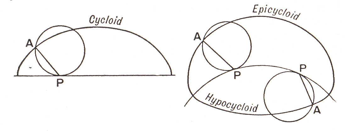
If the circle rolls, without slipping inside or outside a circular arc, the locus of a point on its circumference is termed respectively a Hypocyloid or a Epicycloid. The three curves are shown in the diagram above.
Gears with cycloidal teeth suffer from the following disadvantages and are little used in modern engineering practice:
- The center distance must be exact in order to achieve a uniform Velocity ratio.
- The Pressure angle i.e. the direction of the normal teeth between the teeth,varies during the contact of one pair of teeth.
- The teeth on small wheels will be narrower and hence weaker at the root than at the Pitch Line.
Involute Teeth
The outline of a tooth can be traced out by a point on a cord which is unwrapped from a circle (Known as the Base Circle ):
- The whole form of the tooth is outside the Base Circle and the common Normal at the point of contact is the common tangent to the Base Circle.
- The path of contact lies along the common tangent.
- The Pressure Angle is constant.
- The center distance for mating gears can be varied, within limits, without upsetting the Velocity Ratio.
- The teeth are thickest at the root which adds strength.
The Calculation of the Path of Contact
The limiting points of contact are J and K where the addendum circles cut the common Tangent LM to the base circles. If R and r are the Pitch-circle radii then:
also
similarly
Interference
The tip of one wheel will undercut the root of a tooth on its mating gear if contact continues outside the common tangent LM to the base circles. In a set of gears, this is most likely to occur between teeth of the largest gear wheel, acting against those of the smallest pinion.
The condition for no interference is that PK < PM.
Interference can be eliminated by a combination of:
- Increasing the angle of obliquity
- Decreasing the addendum of the larger wheel and increasing that of the pinion in such a way as to maintain the same working depth. (i.e. modified teeth)
- Increasing the angle of obliquity and reducing the addenda of all gear wheels (i.e. stub teeth)
- Mating at increased center distances.
Spiral or Skew Gears
These are used to transmit motion between non-intersecting, non-parallel shafts. The gears must be situated at the shortest distance between the shaft axes and the shaft angle is the angle through which one shaft would have to be rotated about the center distance to bring it parallel to the other. The direction of rotation will then be opposite.
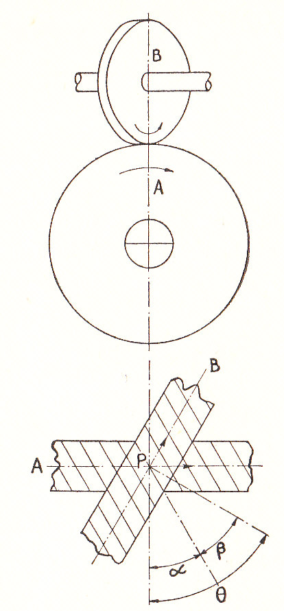
- The diagram shows two skew gears A and B.
- The lower diagram represents the planes of the teeth in contact at the Pitch Point P
and
are the Spiral Angles of the teeth on A and B, respectively.
- For teeth of the same hand
(Note. A Shaft angle of
corresponds to a reversal of direction for one of the wheels)
- The Normal Circular Pitch p (measured normal to the tooth helix) is the same for both wheels and is related to the circular pitches
and
(measured round the Pitch Circle) as follows:-
- The Normal Diametral Pitch
is defined as
- By analogy with plane involute gears, the Pitch circle diameters are then: (14)
and
where and
are the number of teeth.
- The Central Distance
- If
is the friction angle then it can be shown that the maximum efficiency is obtained when :
(16)
Worked Examples
To see the workings of the following examples please click on the red buttons.
Example 1
- What is the condition that must be satisfied if the velocity ratio between a pair of spur gears is to remain constant during the period of contact between a pair of teeth?
- A pair of gears having 40 and 20 teeth respectively, are rotating in mesh with the speed of the smaller being 2000 r.p.m. Determine the speed of sliding between the gear teeth faces at the point of engagement, at the Pitch Point and at the point of disengagement, if the smaller gear is the driver. Assume that the gear teeth are of 20-degree involute form, that the addendum length is 0.200 in. and that the diametral pitch is five.
Example 2
The Pitch Circle diameter of the smaller of two spur wheels which mesh externally and have involute teeth is 4 in. The numbers of teeth are 16 and 32, the pressure angle is 20 degrees and the addendum is 0.32 of the circular pitch.
Find the length of the path of contact of a pair of teeth.
Example 3
Stat the requirements of the mating profiles of two gear teeth for a constant velocity ratio between two wheels and show how these may be satisfied by an involute toothed pinion meshing with an internally toothed wheel.
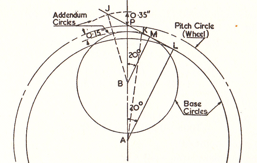
Find Graphically, or by calculation, the length of the path of contact when a pinion with 18 teeth meshes with an internally toothed wheel with 72 teeth, when the angle of obliquity is 20^{0}, diametral pitch is 4 and the addenda on pinion and wheel are 0.35 in. and 0.15 in respectively.
Example 4
A pinion having 20 involute teeth of 4 diametral pitch rotates at 200 r.p.m. and transmits 2 h.p. to a gear having 50 teeth. The addendum on both wheels is one quarter of the circular pitch. The angle of obliquity is .
Find:
- The lengths of the path of approach and of the arc of approach and
- the normal force between the teeth at an instant when there is only one pair of teeth in contact. (U.L.)
Example 5
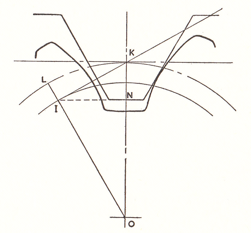
In the following diagram a standard involute rack is shown in contact in its normal position with a pinion with undercut teeth. Make a similar sketch showing what is meant by correction of the pinion. Taking the first point of contact at I on the pinion base circle, show that for no undercutting the maximum addendum of the rack is where d is the pinion pitch circle diameter and
is the pressure angle.
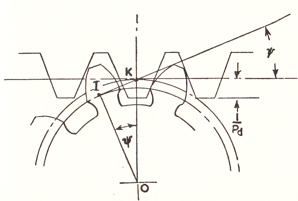
If the pinion has 16 teeth with diametral pitch and
find the minimum amount of correction required when cutting the teeth. If the working depth has the standard value
, find also the pinion addendum and the outside diameter (I.Mech.E.)
Example 6
a) If a pair of spiral gears, A and B , rotate at rates of, respectively, have pitch circles diameters
respectively, and spiral angles of
respectively, show that the sliding velocity along the tooth helices at the pitch point is equal to :
b) Hence show that, if the gear ratio is r, the centre distance C, the normal diametral pitch P and the shaft angle are fixed, then this sliding velocity will be a minimum when:
Example 7
Two shafts A and B are connected by spiral gears so that A rotates at two and a half times the speed of B. The angle between the shafts is . Wheel A has a pitch diameter of 4 in. and has 20 teeth at a spiral angle of
. The teeth on both wheels are of the same "hand" .
Find the spiral angle of the teeth on wheel B and the distance between the shafts.