
Gear Trains
A gear train is a set or system of gears arranged to transfer rotational torque from one part of a mechanical system to another, with some gear ratio performing a mechanical advantage.
Epicyclic gearing or planetary gearing is a gear system consisting of one or more outer gears, or planet gears, revolving about a central, or sun gear.
An analysis of Gear Trains with particular reference to Epicyclic Gears
You're viewing an older version of this page (#3836). View the current version.
Introduction
One of the most common uses of Gear Trains is in the gear boxes of cars. In the simplest form, the crash gear box, a collection of spur gears were arranged to give different ratios of input to output speed and in the case of the reverse gear, change the direction of the output rotation.
The modern synchromesh gearbox is a development working on very similar principles.
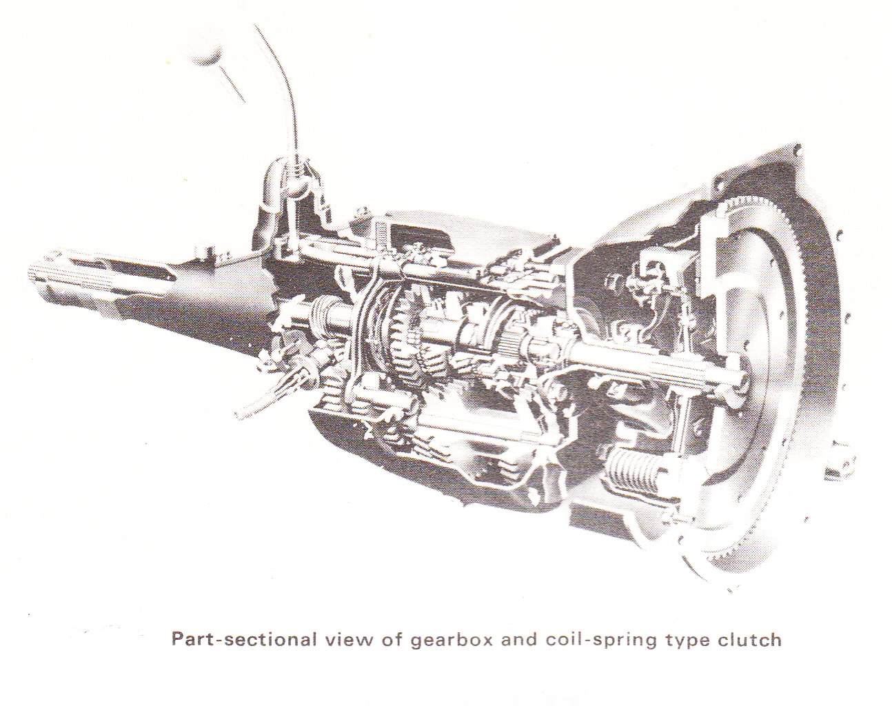
Another, and in many ways more interesting, type of train uses epicyclic gears.Many modern cars use a small epicyclic in the starter motor but much larger and more complicated versions have been used as the main gearbox. Before the 1939 - 1945 war the Daimler Car Company used a "pre-selector" Wilson box.
In more recent years these were fitted to London Transport Buses and they were also to be found in some British Army armoured wheeled vehicles. The gear box, which is driven through a fluid fly wheel, allows the driver to pre-select the next gear to be used and then to make a very rapid change at the right moment. This ability is useful in heavy urban traffic and when driving across uneven country.
Gear Trains on Fixed Axes
The velocity ratio transmitted between two gears is the same as for two pitch circles rolling together. As the circular pitch must be the same for both wheels, the speed ratio is determined by the number of teeth.
i.e.
- The positive sign is taken for Internal gearing
- The negative sign is taken for External gearing.
A Simple train is one of three or wheels connected in series.
- The gear ratio is independent of the size of the intermediate wheels which are called Idlers
- For an odd number of externally geared wheels the direction of rotation of the last wheel is the same as the first.
- For an even number of wheels the direction of rotation of the llast wheel is opposite to that of the first.
A Compound Chains
- When an intermediate shaft carries two wheels connected in series, the train becomes compound. e.g. If
gears with
which is compounded with
which then drives
.
i.e.
Such arrangements can greatly increase or decrease the gear ratio.
- Where the axis of the last wheel is in line with that of the first, the arrangement is known as a reverted train.
Epicyclic Trains.
One or more of the wheels of the gear train are now carried on an arm which itself rotates about the axis of the main wheels.
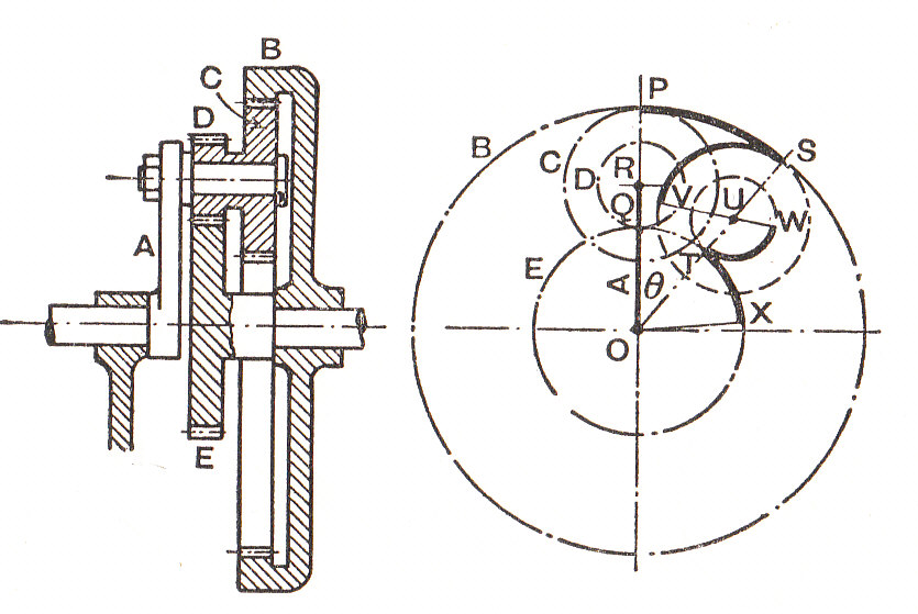
The central main wheel is called the Sun wheel. The wheels carried by the arm are known as The Planet wheels and the outside internal wheel is called the Annulus. In some epicycilic gear trains the "arm" has a number of "limbs" each carrying a planet wheel. In these cases the "arm" may be referred to as the Spider.
There are a number of ways of analysing epicyclic gear trains. Three are described here:
Tabular Method
- The first line of the table is obtained by fixing the arm and then giving one wheel ( e.g. the wheel which later is to be fixed) one revolution.
- Write down the corresponding revolutions of the other wheels from their number of teeth.
- As all the wheels and the arm can be turned about the same axis, an equal number of revolutions may be added (or subtracted) from each wheel.
- Any two lines may be multiplied (or divided) through by the same factor.
- Any two lines may be combined. By these means the given conditions are satisfied and the resulting gear ratio can be determined.
Note. The above may seem confusing and should be read in conjunction with the worked examples and in particular Example (3).
The Relative Velocity Method
If the arm is fixed, then the gear becomes a simple or compound train. Thus the ratio of the speeds of any two wheels can be determined by using the methods of paragraph (2).
i.e.
(If the arm were fixed.)
Where there is an intermediate shaft between and
which carries two wheels
and
which are fixed together and arranged so that
drives
and
drives
, then the above equation can be modified to:
which can be calculated from the number of teeth etc.
For simple epicyclic operating with a fixed annulus there is nothing to choose between the above two methods. However if all the wheels are moving or when dealing with compound epicyclic, the second method gives a quicker and more direct solution. A comparison of the methods can be made from Examples (3) and (4)
The Determination of Torques
There are normally three torques acting on an epicyclic gear. These are:
the input Torque (in the sense of rotation of the input shaft)
the output torque (opposite to the sense of rotation of the output shaft)
the Torque on the casing.
Assuming the casing to be fixed,
From considerations of the power and for equilibrium ( Taking signs into account )
- For input and output shafts to have the same direction of rotation
(numerically)
- For input and output to have opposite directions of rotation.
(numerically)
When there is no fixed wheel, there will, in general be three torques to satisfy the following equations. Of the torques one can be found from the horse-power and speed.
And
Alternatively, the forces acting on each wheel (or compound pair) may be analysed separately, since if the gear is running at constant speed, there is no resultant force and no resultant torque on any intermediate wheel.
Example 1 [imperial]
Two shafts and
in the same line are geared together through an intermediate parallel shaft
. The wheels connecting
and
have a diametral pitch of 9 and those connecting
and
4, the least number of teeth on any wheel being not less than 15. The speed of
is to be about but not greater than
the speed of
and the ratio of each reduction is the same.
Find suitable wheels, the actual reduction and the distance of shaft from
and
.
Since the speed ratios between and
and between
and
are to be the same and the overall reduction is greater than 12 then, using and adapting equation (1)
i.e.
As and
are in a straight line, the centre distance between each and
must be the same. Also the diametral pitches are 9 and 4.
i.e.
From the Speed Ratios and
Substituting into equation (#1), And
It follows that is the lesser and since it must be an even number greater than 15, try
. Then
from the speed ratio.
Example 2 [imperial]
The lead screw of a lathe has a right-hand single thread with a pitch of in. The smallest change wheel has 20 teeth, the largest 120 teeth and the number of teeth on intermediate sizes increases in steps of 5.
Find a gear train suitable for connecting the spindle and the lead screw when:
- a) A right hand screw with 26 threads per inch is to be cut.
- b) A left-hand screw with 35 threads per inch is required.
- a) Since the required screw is right-handed and has 26 threads per inch, it follows that them spindle must make 26 revolutions whilst the saddle moves 1 in. towards the headstock. But the saddle will move 1 in. towards the headstock when the lead screw makes 4 revolutions. Hence the spindle must make 26 revolutions while the lead screw makes 4 revolutions.
Let of the spindle and
of lead screw
Then,
The only wheel in the set those number of teeth is a factor of 13 is that with 65 teeth
The wheels would be arranged as shown in the diagram (a). It can be seen that the spindle and the lead screw revolve in the same direction.
- b)Since the required screw is left handed and has 35 threads per inch, the spindle must make 35 revolutions while the saddle moves 1 in. away from the headstock. The lead screw must therefore make 4 revolutions whilst the spindle makes 35 revolutions in the opposite direction.
The wheels would be arranged as shown in diagram (b)
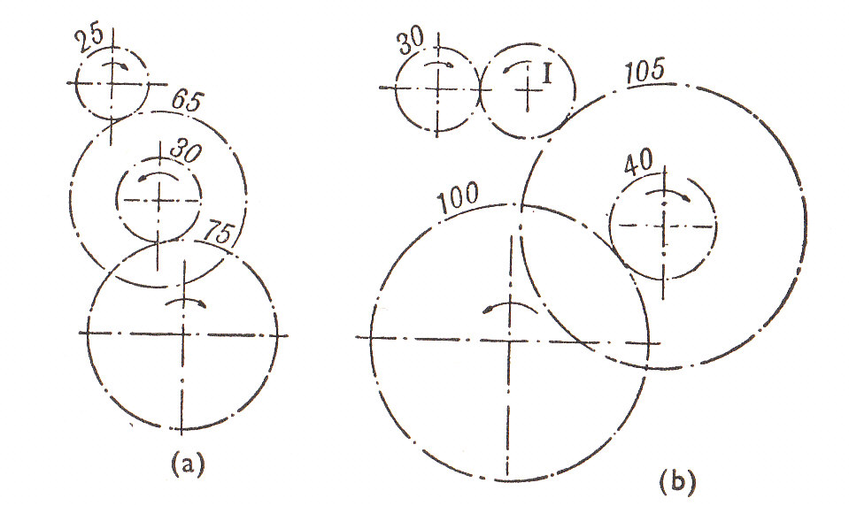
The intermediate or idler wheel is required in order to make the lead screw rotate in the opposite direction to the spindle. As already noted the intermediate wheel does not affect the speed ratio and so a wheel of any convenient size may be used.
Example 3 [imperial]
In the Epicyclic Gear shown the internal wheels and
and the compound wheel
rotate independently about the axis
. The wheels Band
rotate on pins fixed to the arm
. The wheels all have the same pitch and the numbers of teeth are :
and
18,
28, and
26.
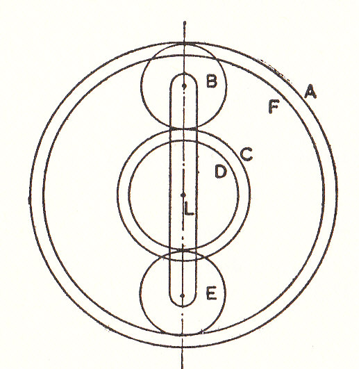
If makes 150 r.p.m. clockwise, find the speed of
when :
- a) The Wheel
- b) The Wheel
Since the pitch is the same for all the wheels, the diameters are proportional to the number of teeth.
And
The required speeds can be calculated from the following Table. The wheels and
are omitted since they perform only intermediate function.
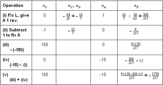
- a) From line (iii)
Clockwise
- b) From line (v)
Anti-clockwise
- a)
Clockwise
- b)
Anti-clockwise
Example 4
In the epicyclic gear train shown in the diagram, wheel and wheel
(30 teeth) are fixed to a sleeve
which is free to rotate on spindle
.
(24 teeth) and
(22 teeth) are keyed to a shaft which is free to rotate in a bearing on arm
.
has 70 teeth.
has 15 teeth and is mounted on a shaft
which rotates at 100 r.p.m. Spindle
makes 300 r.p.m. in the same direction as
. All the teeth are of the same pitch.
Find the speed and direction of rotation of .
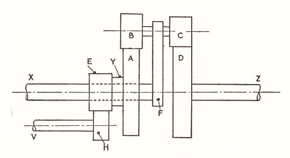
Note: is not part of the epicyclic since it is turning on a fixed shaft not in line with the axis of the arm.
In this example it is better to use the Relative Velocity Method which was described earlier. (See equation (2). It can be seen from the diagram that is the Arm.
The Speed Ratio to
=
But if the arm were fixed: The Speed Ratio to
=
But is mounted on shaft
and rotates at 100 r.p.m. It meshes with
which has twice as many teeth and so
rotates at 50 r.p.m. in the opposite direction to
.
Thus,
i.e. 11.7 r.p.m. in the opposite sense to both and
.
- Speed of
is 11.7 r.p.m. in the opposite sense to both
and
.
Example 5 [imperial]
A gear train is shown in the diagram in which the shaft rotates at 500 r.p.m. Solid with shaft
is the arm
on which the compound bevel wheels
and
can revolve freely together. Wheel
meshes with wheel
and wheel
with wheel
which is also solid with the spur wheel
, the latter meshes with
on shaft
which rotates in the opposite direction to
. The bevel wheel
is fixed by keying to the support.
The number of teeth on wheels and
are 20, 27, 32, 24, and 30 respectively.
Determine the number of teeth required on wheel to give a speed reduction of 20 to 1 between shafts
and
.
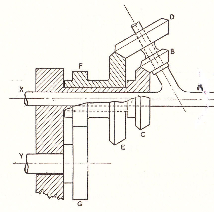
Where bevel gears are turning on axes which are not parallel to that of the Arm, it is difficult to attach any sign to their direction of rotation. For this reason they are omitted from the table below and they are merely made use of to determine the speed of when
is fixed and
is rotated by 1 rev.
Note that the arm is integral with
and that
is outside the epicyclic.
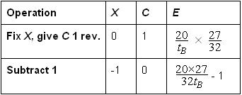
is rotating with
and the speed of
(and
)
(For a speed reduction of 20 to 1.) Taking the value for
from the Table as -1,
Hence,
- The number of teeth required on wheel
Example 6 [imperial]
In the epicyclic gear unit shown in the diagram the input shaft is attached to the planet carrier.
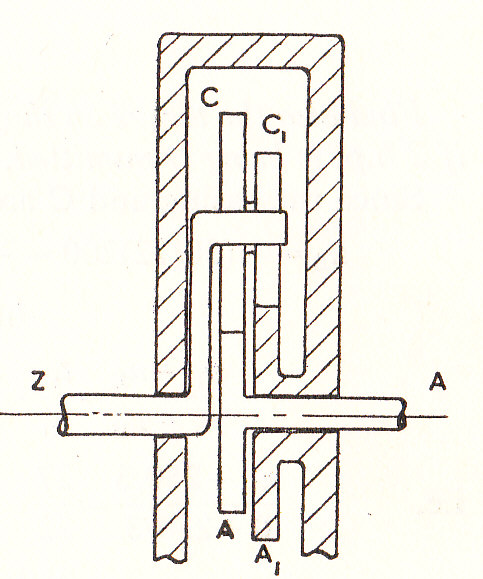
and the output shaft to the Sun wheel
. Sun wheel
is fixed to the casing and does not rotate whist the planet wheels
and
are compounded and rotate together.
If all teeth are the same pitch and and
each have 20 teeth, find the teeth on
and
so that the output shaft runs in the reverse direction and at half the speed of the input shaft.
If the input shaft transmits 14 h.p. at 1500 r.p.m.and the efficiency of the unit is 96% calculate the input and output torques and the fixing torque of the casing.
Tabulate the speeds as follows:
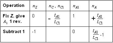
From the question :
But from the above table:
Thus,
But since the pitch is the same for all wheels:
Since both and
have 20 teeth equations (1) and (2)(- from Example (5)) can be solved to give:
and
From the question, and so
The torques at both input and output are obtained from the horse-powers. (1 h.p. = 550 ft.lb./sec. or 33000 ft.lb./min.)
And allowing for the efficiency of the system:
The fixing torque is the sum of the input and output torques for opposite directions of rotation. ( See equation (4))
Fixing Torque =
and
and
- Fixing Torque =
Example 7 [imperial]
The diagram shows a system of gearing. The casing is fixed. Wheel
is keyed to shaft
. Wheels
and
are fixed to each other and are free to rotate on shaft
. Wheel
is also free to rotate on shaft
. Wheels
and
are fixed to each other and are free to rotate on a pin mounted on wheel
. The number of teeth on the various wheels is shown on the diagram and all the teeth are of the same diametral pitch.
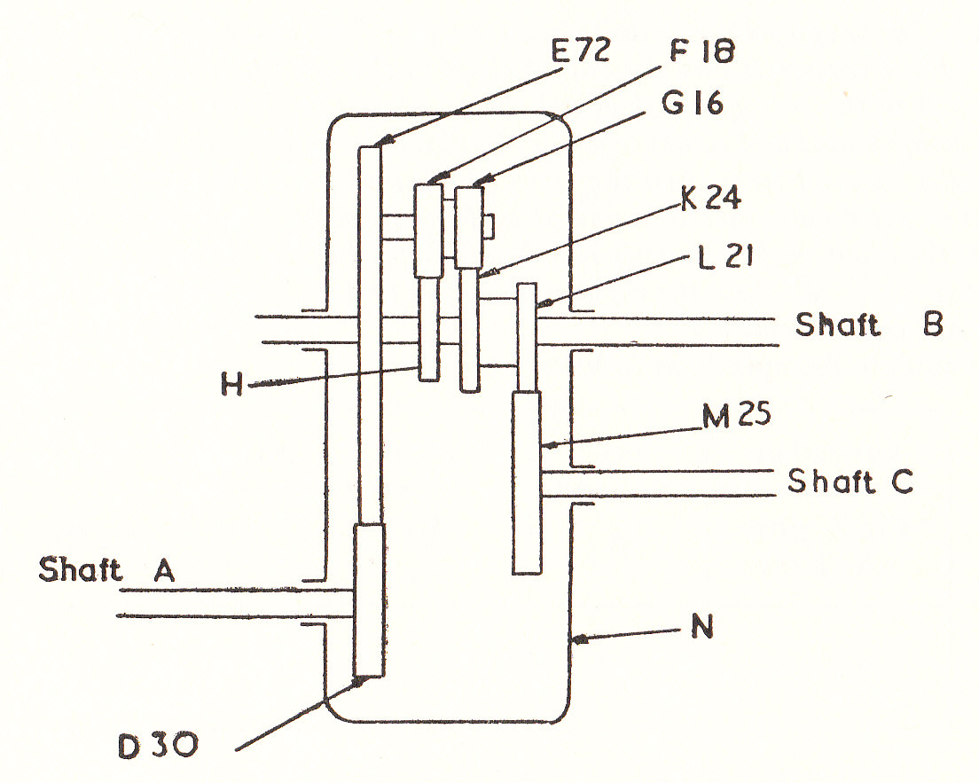
If rotates at 200 r.p.m., whilst
is held stationary, find the speed of
.Find also the torque on shaft
to hold it stationary under these conditions if 2 h.p. is being transmitted.
As the casing and shaft are fixed,it can be seen that both
and
are fixed. Wheel
will turn at a slower rate than wheel
and in the opposite direction.
(
is the "arm")
By inspection,
Using equation (3), i.e.
Thus,
As is keyed to shaft
the above is also the speed of the shaft.
The torque on shaft is given by:
The tangential force between the teeth of and
is given by:
Neglecting all losses and since no torque is absorbed by the compound wheel it is possible to take moments about the centre of the wheel. (see diagram (a))
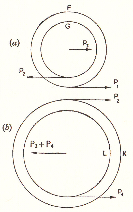
Similarly by taking moments about the centre of the compound wheel (see diagram (b))
Then,
Check:
The above answer can be checked as follows.
This acts on at a radius proportional to
.
By moments about the axis of the force between
and
Thus,
Which is of course what was given in the question.
- The speed of
- The torque on shaft