
Belt and Rope Drives Brakes
Power is the time rate at which work is done or energy is transferred. In calculus terms, power is the derivative of work with respect to time.
An engine or motor is a machine designed to convert energy into useful mechanical motion.
Centrifugal force represents the effects of inertia that arise in connection with rotation and which are experienced as an outward force away from the center of rotation.
A band brake is a brake in which the frictional force is applied by increasing the tension in a flexible band to tighten it around the drum.
The Theory behind Belt and Rope drives using both Flat and Grooved pulleys. Included in this section are drum brakes
You're viewing an older version of this page (#3845). View the current version.
Introduction
Where power has to be transmitted between two shafts which are at a distance apart, a belt or rope drive is frequently used. In most cases the power transmitted relies upon the friction between the rope or belt and the rim of the pulley.
However in the case of toothed belts and chains, friction does not play a beneficial part, no slip is allowable and a precise relationship between the movement of the pulleys is obtained. Examples of this sort of drive are the cam belt used on many modern engines and the simple bicycle chain.
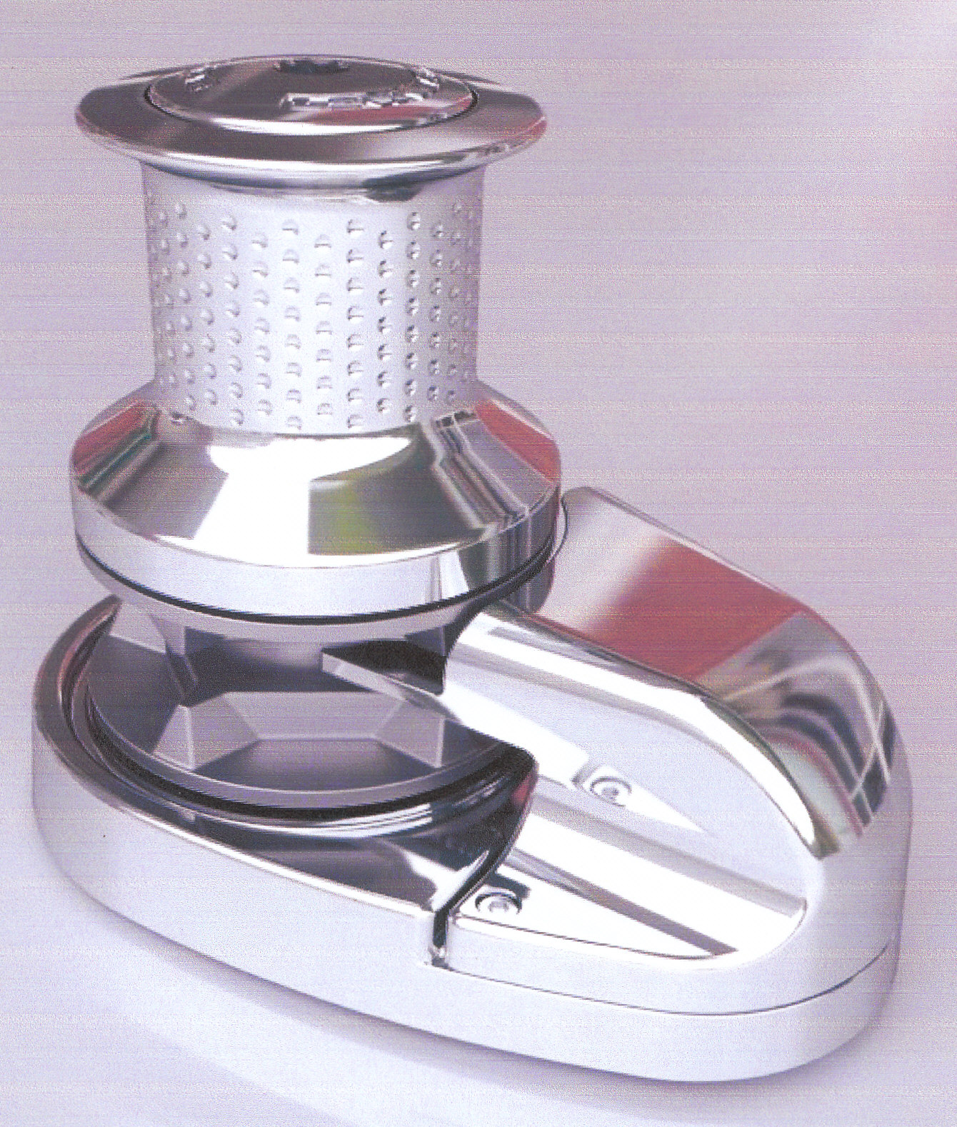
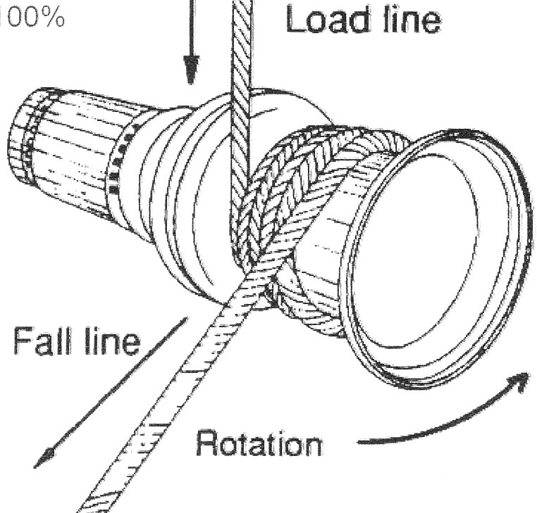
Rope drives, as such, are not now much used, but the principle is alive and well in shipping where capstans and windlasses are used to tighten ropes and chains.
Flat belts were used extensively in both agriculture to connect both steam and early tractor to static machinery and also in early factories where all the machinery in a building was powered by one engine driving a series of shafts, pulley wheels and belts. These belts could be long enough to transmit power from one floor of a building to the one above. A selection of arrangements of belt drives is shown in the diagram below.
Today the majority of belts in use are Vee often used in sets of three,side by side. A modern development seen on some cars, is a flat belt with a series of mini Vees on the inner surface.
Flat Pulley Drives
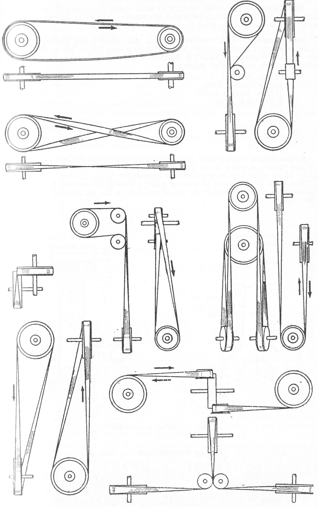
Although described as Flat many pulleys used with flat belts are actually slightly curved so that the diameter at the middle is slightly larger than that at the ends.
This helps to keep the belt on the pulley.
It is also normal on long belts to twist them as shown in the diagram. This can be seen in the above diagram and increases the angle of contact between the belt and the pulley. Another technique to increase the angle is the use of idlers which are small pulley wheels which help to control slack in the belt.
At Low Speed
The maximum torque that can be transmitted between the belt and the pulley occurs when limiting friction is developed around the arc of contact.
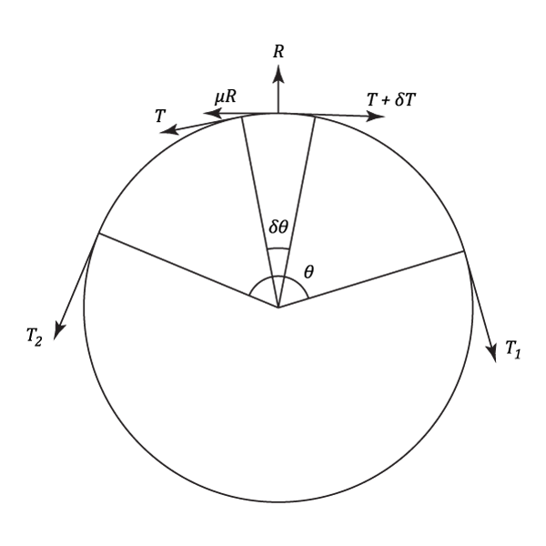
The forces acting on a short length of the belt which subtends an angle of at the centre of the pulley, are shown on the above diagram.
Resolving Tangentially:
Thus in the limit:
Resolving Radially:
Drawing of pulley showing tensions and radial :
therefore,
Adding
Hence in the limit:
Combining equations (#1) and (#2) and eliminating :
This equation can now be integrated over the whole arc .
Or,
This is the maximum possible ratio of tensions between the "tight" and "slack" sides of the belt and consequently for a drive between pulleys of unequal diameter, the smaller angle of lap should be used.
It should be noted that in some applications such as Capstans and Windlasses the rope is passed completely round the pulley, sometimes more than once.
Allowance for Centrifugal Force
The analysis above assumes, in effect, that the belt and pulley is at rest. In practice this is not often the case when the belt is subjected to a centrifugal force as if passes round the pulley.
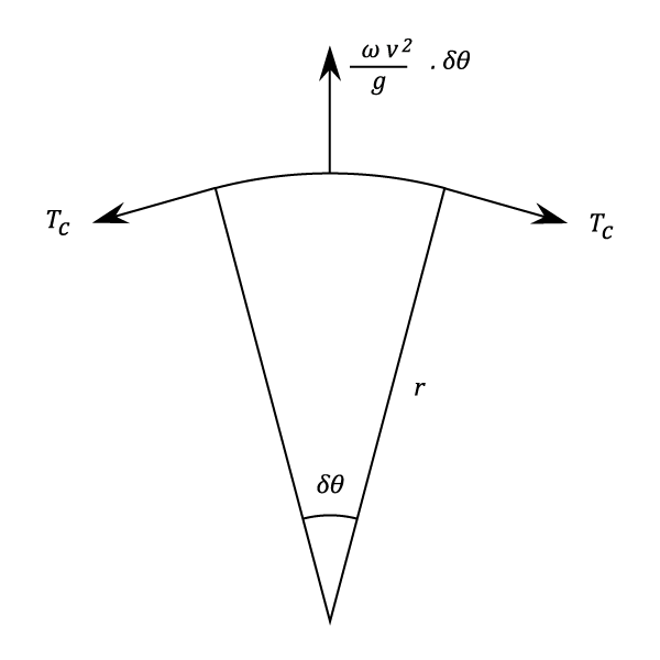
If is the weight of a unit length of belt and
is the linear belt speed, then the force on an element:
This force has to be balanced by a tension in the belt. The value of this tension is obtained by resolving radially.
Hence
The Total Tensions on the two sides are then:
where and
are the tensions transmitting the power and are calculated from equation (#2).
Equation (#2) can now be written as:
Grooved Pulley Drives
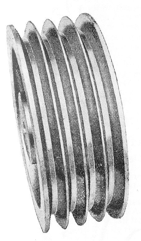
Although rope can be used for such drives, the vast majority rely on V-belts. In many applications the pulley has more than one groove and there are obviously an appropriate number of belts.
Assuming that the included angle of the groove is , the Normal Reaction
is given by :
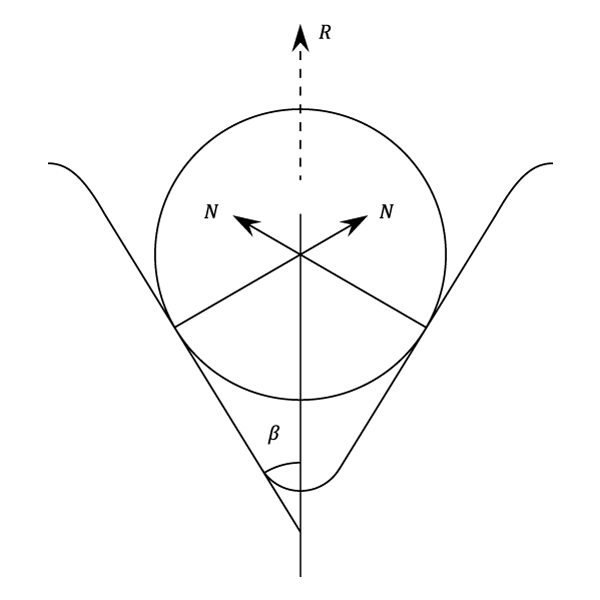
But Friction
(using the above equation)
Where
The analysis now becomes similar to a flat pulley where is the equivalent coefficient of friction.
The Power Transmitted
Two sets of equations are given below to cater for both measurement systems:
Imperial
The horse-power transmitted
Using equation (#3) this can be rewritten to give the maximum power transmitted i e.
And using equation (#5)
S.I.Units
Power transmitted in Kilo Watts
Combining with equation (#3),
And using equation (#5)
For a limiting value of , it can be shown that the above equations for the power transmitted have a maximum value when:
i.e.
It is usual to assume that the mean tension is constant at all speeds and is therefore equal to the initial tension
.
If is neglected it then follows from equation (#3) that:
And hence the power transmitted at a given speed is proportional to the initial tension.
The principles of Band Brakes are similar to those of the preceding paragraphs, giving, in this case the braking torque which can be applied to a rotating drum.
There has been a slow but steady movement away from the use of Shoe and Drum Brakes by the automotive industry. The method of tackling problems associated with this type of brake can be seen in Example (15)
Example 1 [imperial]
A number of trucks are to be hauled by a rope passed round a hydraulic capstan; assuming a coefficient of friction of 0.25 between the rope and the capstan and a constant manual pull of 30 lb., derive an expression for the maximum pull on the trucks in terms of complete turns of rope round the capstan.
What will be the horse power exerted by the capstan under these conditions when there are turns of rope and it is being wound off at 100 ft/min.?
From equation (3)
From the question:
,
and
From which:
When ,
Using equation (7) the horse-power of the capstan is given by:
To which must be added the power supplied manually which is: So the horse-power taken by the trucks
The horse power taken by the trucks
Example 2 [imperial]
A flexible elastic band passes over a pulley 20 in. in diameter which is supported in fixed horizontal bearings.
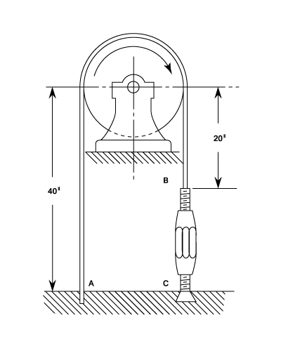
The end is anchored to the ground and the end
is held by a turnbuckle whose lower end is also anchored to the ground at
.
The turnbuckle, which has right-hand left-hand square-threaded screws of external diameter and
pitch is used to tighten the band on the pulley until the couple on the turnbuckle is 100 lb.in.,the tension on the band being then assumed to be uniform.
The pulley is now rotated clockwise against the frictional resistance of the band. Assuming that the total length of the band now remains unchanged, find the couple required to produce this rotation.
The coefficient of friction between the screws and nuts = 0.15 and between the band and the pulley = 0.25. Neglect friction at the bearings and any extension between and
.
For the first part of this question it may be necessary to look the pages on "Screw threads "and in particular equation (14)
The Couple on the turnbuckle is:
where is the initial tension in the band.
and
Substituting into equation (#1)
When the pulley is rotated, becomes the "tight" side (tension
) and
the "slack" side (tension
).
Equation (3) states that:
The stretch in the band is proportional to the product of the tension and the length and for a constant total length:
Using the results of equations (#2) and (#3) this can be integrated and re-written as:
Simplifying,
And from equation (#3),
Hence the couple on the pulley
The couple on the pulley
Example 3 [imperial]
In the torque amplifier shown in the diagram, the input and output shafts rotate at the same speed and in the same direction. They are connected by a flexible band, attached to radius arms, which make 1.25 turns around a coaxial drum. The drum is driven at high speed by an electric motor.
If the coefficient of friction between the drum and the band is 0.21, find the torque required at the input shaft to overcome a torque of 1.5 lb.ft. at the output shaft. If the drum speed is 5 r.p.s. and the shaft speeds are 2 r.p.s. find for the above conditions, the energy lost in drum friction expressed in ft.lb./sec.
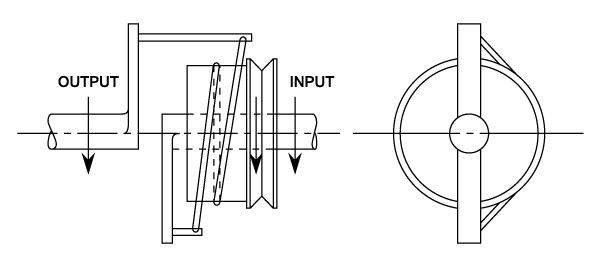
Let both the input and output arms be of length and note that the "tight" side of the band is connected to the output side.
The tension at input is given by:
Using equation (3) the tension at input is given by:
From the above equation the input torque, is given by:
Substituting from equation (1 in the above example),
The torque on the drum is the difference between the input and output torques of which the output value is given as 1.5 lb.ft.
The energy lost = the torque on the drum the speed of slip
- The torque is
- The energy lost is
Example 4 [imperial]
An elastic belt makes contact with a pair of flat pulleys over arcs of , the coefficient of friction being 0.45. The initial tension is 90 lb. and it may be assumed that the sum of the tensions on the two sides remains constant.
Find the difference in the tensions at which the belt slips on the pulleys. If the belt is 1 inch wide and thick and the elastic modulus for the material is 35,000 lb./sq.in.estimate the effect on the maximum tension difference which would be caused if the pulley centre moved together by
in., if they were initially 3 ft. apart.
From equation (3) the ratio of the tensions at slip are given by:
But twice the original tension = 180 lb.
and
The difference in the tensions
If the pulleys are now move together by in.the decrease in stress = the strain
the modulus.
The decrease in Stress
The decrease in initial tension = stress area
Thus the new initial tension is 90 - 30.4 = 59.6 lb.
But the running tensions ( and hence the maximum tension differences) are proportional to the initial tension. ( See paragraph on "Power Transmitted") and hence the maximum tension difference is reduced in the same ratio as the initial tension,
i.e. The new tension difference
- The difference in the tensions is
- The effect on the maximum tension difference is
Example 5 [imperial]
An open belt connects two flat pulleys. The smaller pulley is 1 ft. in diameter and runs at 200 r.p.m. The angle of lap on this pulley is and the coefficient of friction between belt and pulley face is 0.25. The belt is on the point of slipping when
h.p. is being transmitted.
Which of the following alternatives would be more effective in increasing the power which could be transmitted:
- Increase the initial tension in the belt by 10%
- Increase the coefficient of friction by 10% by the application of a suitable dressing onto the belt.
From equations (7) The horse-power transmitted
Combining this with equation (3) The horse-power transmitted
Assuming that:
And using equation (3) again,
Substituting the above into equation (#1)
The horse-power transmitted
from the above it can be seen that the power transmitted will increase by the same proportion as and as a result an increase in the initial tension of 10% will increase the power transmitted by 10%.
The effect of increasing the coefficient of friction is to alter the value of
The original value of
The modified value of
The ratio of the increase in h.p.transmitted is thus:
Thus the effect of treating the belt would be an increase in power transmitted of 9 % and it would therefore be clearly preferable to increase the initial belt tension.
Example 6 [imperial]
A leather belt in. thick connects two pulleys of 3 ft. 2 in. and 1 ft. 9 in. diameters, carried on parallel shafts at 11 ft. 6 in. centres; the speed of the larger pulley is 240 r.p.m.. The coefficient of friction is 0.25 and the maximum permissible load on the belt is 260 lb.
Find the maximum horse-power and the necessary initial tension.
Plot on a base of initial mean tension, curves showing the horse-power which can be transmitted
- Maximum loading but neglecting the possibility of slip.
- Limitations due to slip but neglecting the possibility of overloading the belt.
Hence determine the permissible range of initial tension if is to be transmitted.
The difference in pulley diameters is 38 in. - 21 in.= 8.5 in. and therefore the smallest angle of lap, is given by:
Therefore,
Allowing for the thickness of the belt, the velocity of the belt is:
From equations (3) and (7), Horse-power
Using equation (3) again,
- Allowing for maximum loading
= 260 lb. and hence:
From equation (7), Horse-power
Substituting in values from above:
Horse-power
- Allowing for limitations due to slip
From equation (3),
Since it can be shown that:
Substituting in equation (8) gives, Horse-power
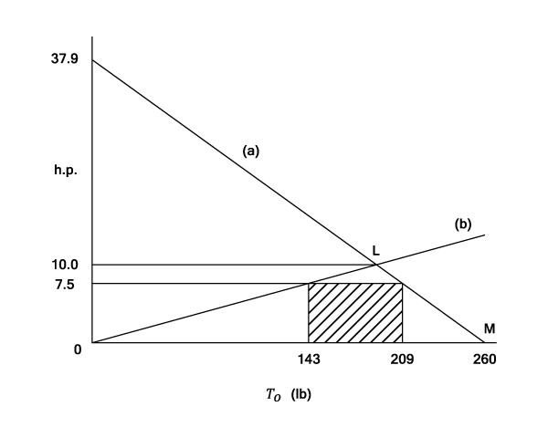
The only operating parts of the lines given by the two conditions given in the question are below OLM and the range of for 7.5 h.p. is from 143 lb. to 209.lb.
Example 7 [imperial]
A small pulley of radius on a line shaft drives a large pulley of radius
on a machine vertically below it, the centre distance being a distance
.
Show that slipping will be equally likely to occur at either pulley, if the tension in the belt where it runs over the larger pulley is given by:
Where is the weigth of a unit length of belt and
The length of belt between the pulleys is and resolving vertically for each side of the belt.
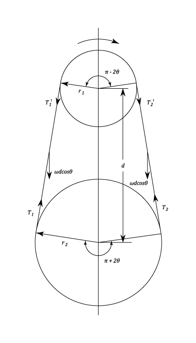
Similarly:
And,
From Equation (3)
And
Substituting from equations (#1) and (#3) in equation (#4)
Eliminating from the above equation by using equation (#2)
Example 8 [imperial]
A leather belt transmits 25 h.p. from a pulley 3 ft. in diameter which runs at 300 r.p.m.; the density of the belt is 0.035 lb/cu.in. and the maximum stress is not to exceed 350 lb/sq.in.
In the belt is in. thick, find the least possible width required.
From Equation (9), Horse-power
The velocity of the belt,
From equation (4),
Where is the weight per ft. length
Note. The density thickness and width of the belt are given in inches. In the above equation we require the weight of 1 foot i.e.12 inches.
As the maximum stress must not exceed 350 lb./sq.in
Putting equations (#2) (#3) and (#4) into (#1)
Horse-power (given)
- The least possible width required is
Example 9 [imperial]
An open belt drive connects two pulleys of 48 in. and 20 in.diameters, on parallel shafts 12 ft. apart. The belt weighs 0.6 lb/ft length and the maximum tension in it is not to exceed 4r500 lb. The coefficient of friction is 0.3.
The 48 in pulley, which is the driver, runs at 200 r.p.m.. Due to belt slip on one of the pulleys, the velocity of the driven shaft is only 450 r.p.m..
Calculate the torque on each of the two shafts, the horse-\b{ power transmitted} and the horse-\b{power lost} in friction.
What is the efficiency of the drive ?
Slipping will occur on the driven pulley since this has the smaller angle of lap. Hence the belt speed, , is calculated for the larger pulley.
Centrifugal Tension,
Useful Tension :
Angle of lap, on the Driven pulley (radians)
Slack side tension, . From equation (3)
Output Torque ( From equations (#1) and (#2))
Input Torque,
Output Horse-power,
Input Horse-power (From equation (2),Example 7)
Frictional Horse-power=Input h.p. - Output h.p. = 1.0
The efficiency of the drive is output/input
- The Input Torque is
- The Output Torque is
- The efficiency of the drive is