
Engine Governors
Centifugal and Inertia Engine Governors
You're viewing an older version of this page (#3555). View the current version.
Introduction
The function of a Governor is totally different to that of a Flywheel. The former is required to control the mean speed of a engine over a period of time as opposed to a flywheel which is used to limit the almost inevitable fluctuations in speed, which occur during one cycle. A good example of this is the single cylinder Four stroke engine. There is only one power stroke to two revolutions of the crankshaft. Without a flywheel, the speed would either fluctuate, within one cycle, by an unacceptable amount or the engine would not work at all since the energy stored in the flywheel is required to carry the engine through to the next Power Stroke.

A Boulton and Watt Rotative Engine made in 1797.
The Watt type Governor can be seen at the top of the picture.
A change in load on a engine will almost certainly lead to a change in speed and the Governor is required to alter the supply of energy to the engine to bring the speed back to its original value. This is achieved by connecting the rotating parts of the governor, through suitable levers, to a sleeve on its axis of rotation. Any change in the speed causes a change in the position of the rotating parts and consequently to the sleeve and this movement actuates the fuel supply valve ( This includes Compressed air; Steam or water) of the particular engine or turbine. This function is of particular importance in A.C. electric generators since it is important to maintain the correct number of cycles per second from the generator who's load may change rapidly and unpredictably.
Generally Governors can be classified as either Centrifugal or Inertia
Centrifugal Governors
The effort of the governor is obtained from the change in centrifugal force on (usually) two rotating masses known as Balls, when an increase or decrease in governor speed occurs. Two main types can be distinguished.
Dead-weight Governors
The radius of the ball path is controlled by lever and weights the latter being usually attached to the sleeve as in the (a)"Watt" (b)"Porter" or (c) "Proell" governors.
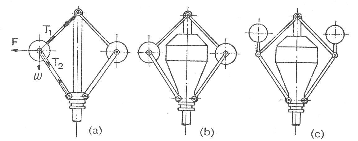
The equilibrium position can usually be determined by considering the forces acting on one ball and the arm or arms to which it is attached. ( See Examples 1,2 and 5)
Spring-loaded governors.
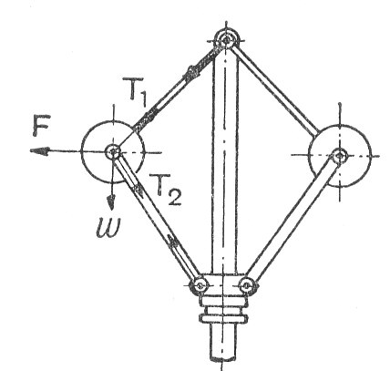
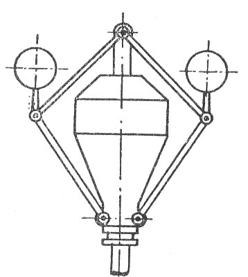
The balls are controlled by springs acting on them or the sleeve. Three examples are shown in the diagram.
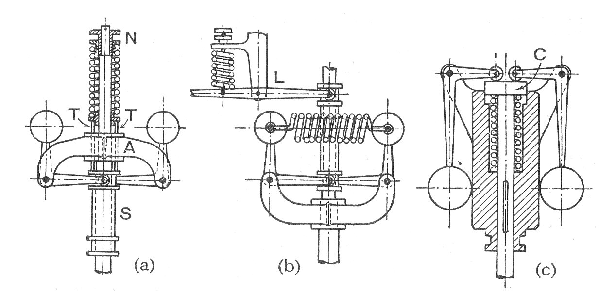
The Hartnell governor (a) is a well known example of this type. Each ball is attached at one end of a bell-crank lever and at the other end to the actuating sleeve. The method of analysis is to take moments about the pivot of the lever ( See Examples 6,7 and 8)
Inertia Governors
Inertia Governors work on a different principle. The governor balls are arranged so that the inertia forces caused by angular acceleration or retardation of the governor shaft tend to alter their positions. The amount of the displacement of the balls is controlled by springs and the governor mechanism to alter the supply of energy to the engine.
The advantage of this type of Governor is that the positions of the balls are affected by the rate of change of speed of the governor shaft. Consequently a more rapid response to a change of load is obtained, since the action of the governor is due to acceleration and not to a finite change of speed. The advantage is offset, however by the practical difficulty of arranging for a complete balance of the revolving parts of the governor. For this reason centrifugal governors are much more frequently used. ( See Example 10)
Definitions
- Controlling Force This is the inward radial force exerted on each ball of a centrifugal governor by the arms, spring, etc. which are attached to it. At any equilibrium speed the controlling force is equal and opposite to the centrifugal force.
- Effort The mean force exerted at the sleeve due to a 1% change in the speed of the governor.
- Power The work done at the sleeve for a 1% change in speed is called "The Power" and is equal to the effort times the sleeve displacement.
- Sensitivity This is defined as the ratio of the mean speed to the speed range of the governor over its limits of operation.
- Stability A governor is said to be stable if there is one equilibrium speed for each radius of rotation r and this speed increases with the radius.
- Isochronism A governor is said to be isochronous is, neglecting friction, the equilibrium speed is the same for all radii of the balls. This implies infinite sensitivity and the governor will always fly to one or other extreme position.
- Hunting The governor is said to hunt if the engine speed is caused to fluctuate continually above and below the mean speed. This is caused by over-compensation of the energy supply due to the governor being too sensitive.
Worked Examples
The working of these examples have been hidden. They can be seen by clicking on the button.
Example 1
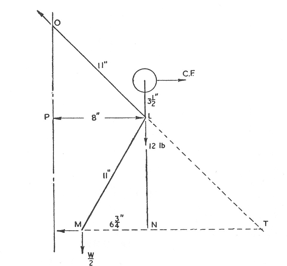
The upper arm of a loaded governor are 11 in. long and are pivoted on the axis of rotation.
The lower arms are also 11 in. long between pin joints but are pivoted to the sleeve at distances of in. from the axis of rotation. Each governor ball weighs 12 lb. and is carried on an extension of the lower arm, the ball centre being vertically above and
in. from the pin joint between the upper and lower arms when the radius of gyration is 8 in.
Neglecting friction, find the load required on the sleeve in order to give an equilibrium speed of 270 r.p.m. for this radius of gyration.
Example 2
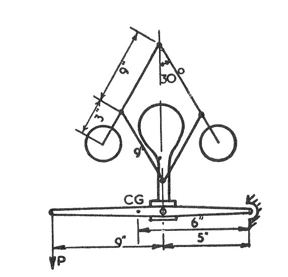
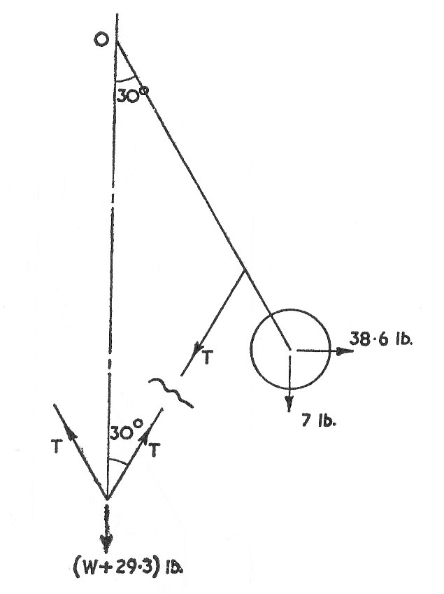
A Porter governor is arranged as in the diagram. The rotating weights are each 7 lb. The sleeve weighs 2.5 lb.and actuates a lever which has a weight of 5 lb.,(Its c.g. is as shown)and which must exercise an operating pull P of 6 lb. The frictional effects of the gear reduced to the sleeve must be loaded so that the governor is on the point of moving out from the given position at 180 r.p.m. Compare the speed at which it would begin to move in from this position. Prove any formula used. (U.L.)
Example 3
In the bowl A shown in the diagram there are eight steel balls B of and resting on the balls is a disc C which is 48 lb. in weight. If the internal surface of the bowl is part of a sphere of 9 in. radius, determine the speed of rotation about the vertical axis at which the balls will move with their centre in a circle of
diameter.
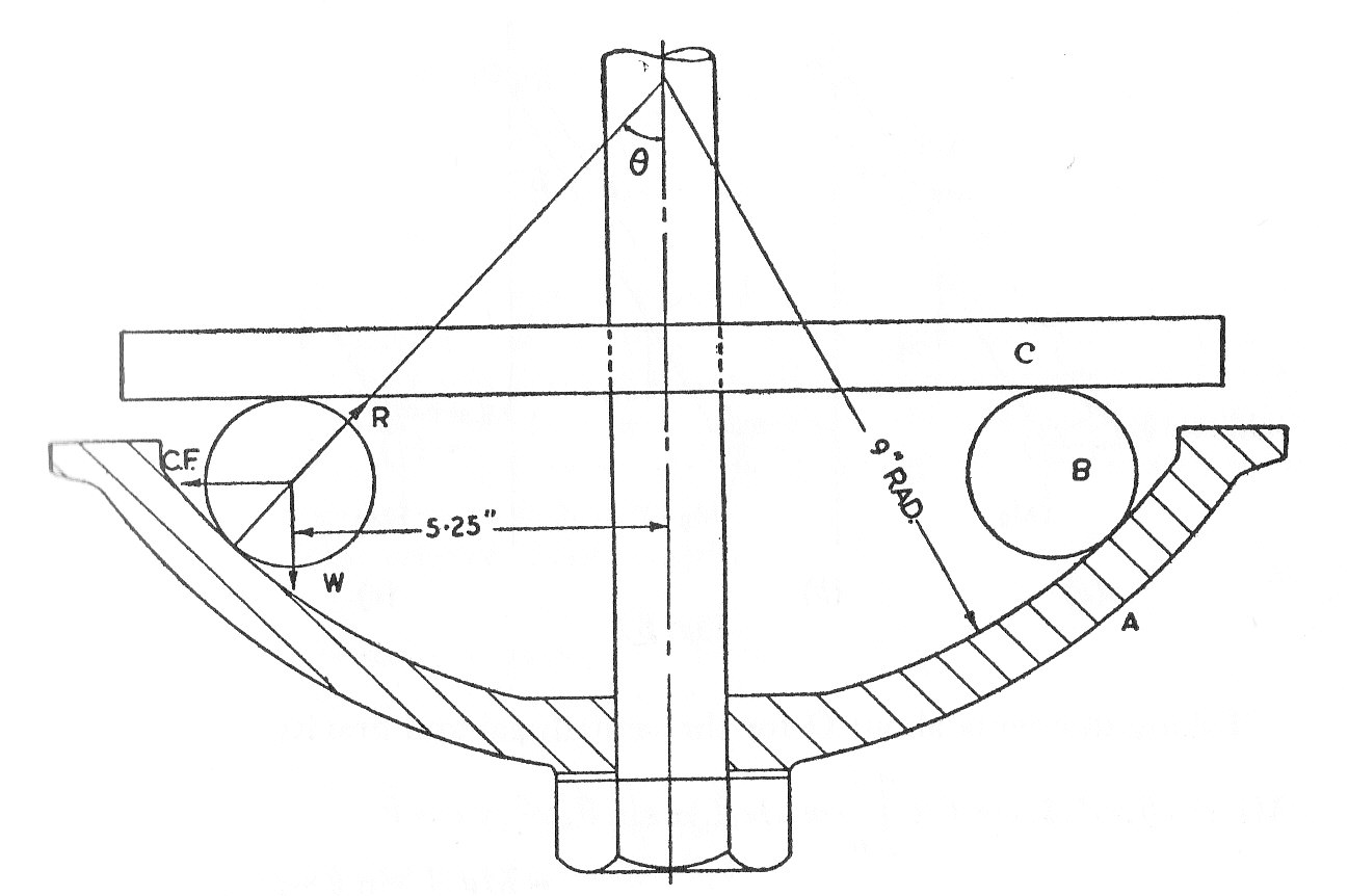
The density of steel is 0.283 lb/cu.in. (U.L.)
Example 4
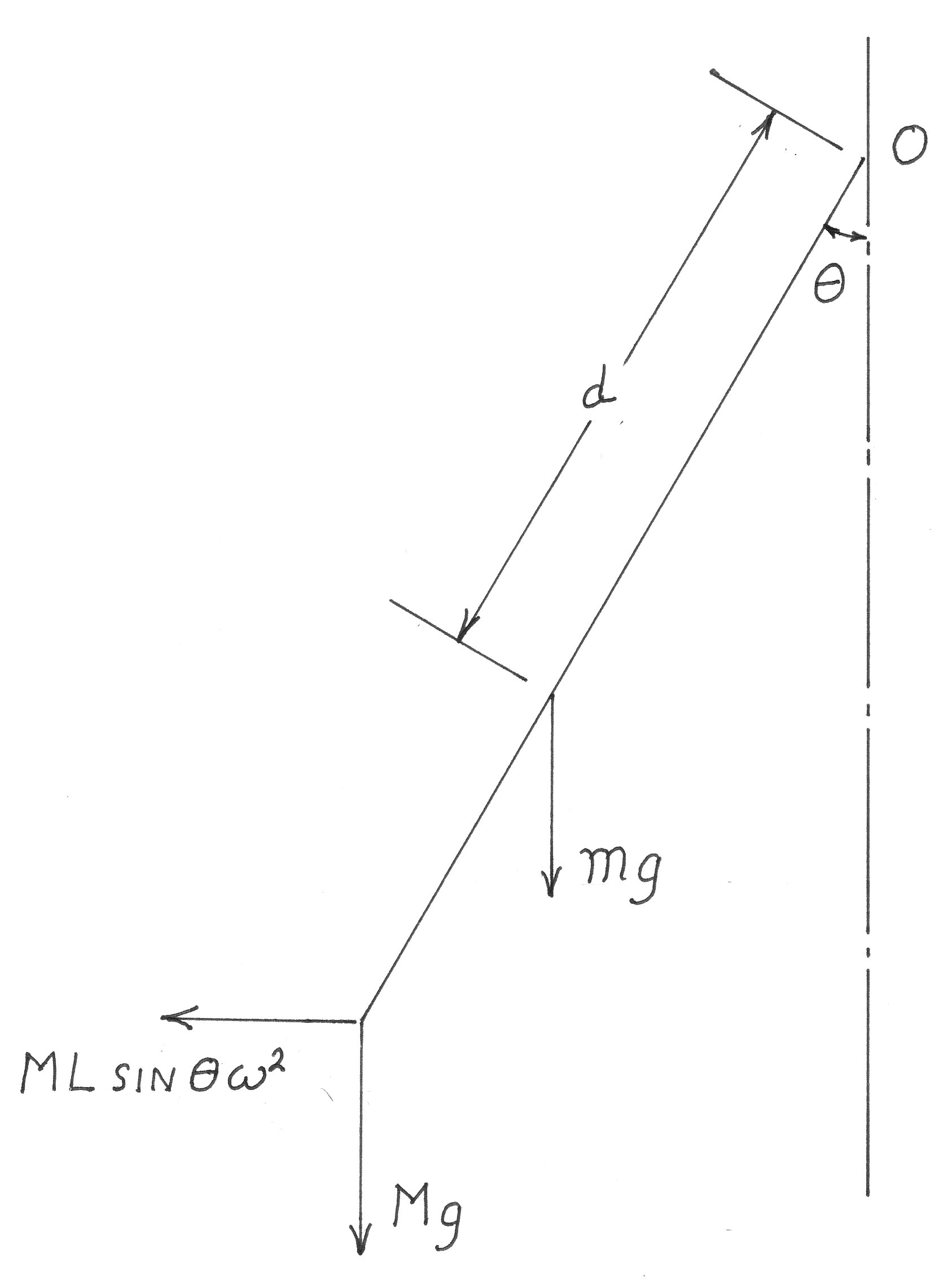
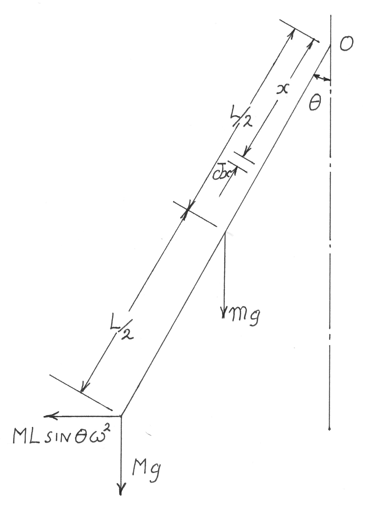
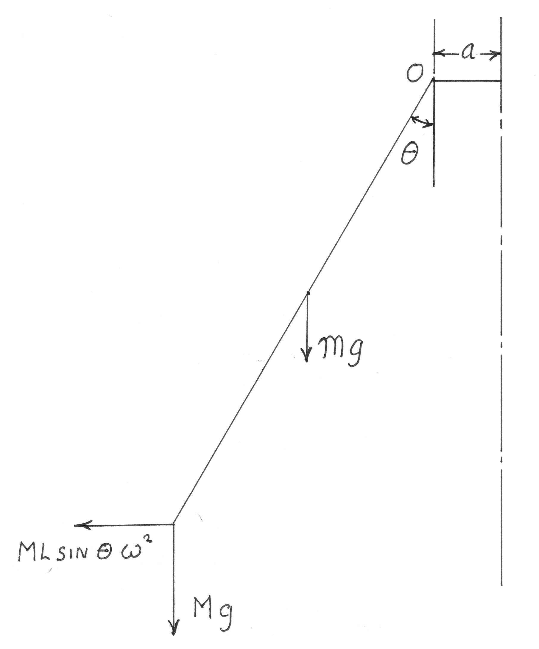
A Watt type governor has an arm of uniform section of length L and mass m and a ball of mass M.
Show that when revolving with an angular velocity of it makes an angle
to the vertical, where:-
Generalise this for the case where the bar is not of uniform section, its radius of gyration about the point of attachment being "k" and its distance from its centre of gravity at the point of attachment being "d"
Generalise also for the case where the bar is of uniform section, but is attached to a point distant "a" from the axis.
In each case the ball is to be regarded as a point mass. (U.L.)
Example 5
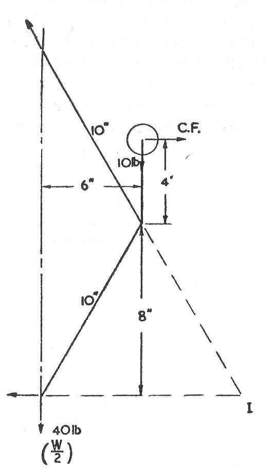
The upper and lower ends of the links of a Proell governor are pivoted on the axis of rotation of the governor.
The upper links are each 10 in. long between centres, the lower links are also 10 in. between centre and carry extension arms each 4 in. long and parallel to the axis when the radius of the ball path is 6 in. Determine the equilibrium speed of the governor for this configuration when each ball weighs 10 lb. and the central load is 80 lb.
Find the alteration required to the weight of the central load if the change of speed in rad./sec. with respect to the change of radius of the ball path in inches is to be 0.65 for the given configuration. What will then be the equilibrium speed? (U.L.)
Example 6
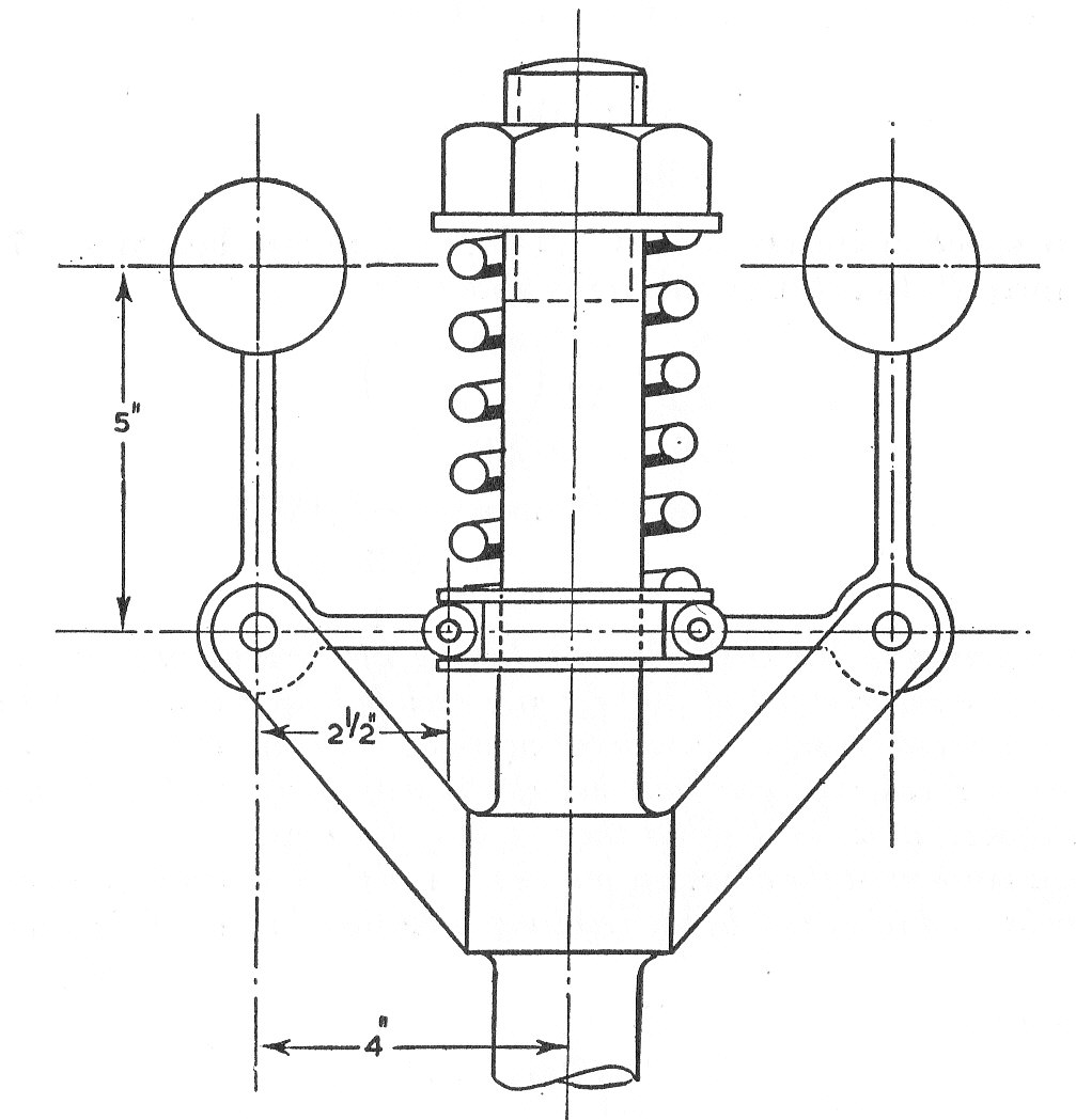
A governor of the Harnell type, having the dimensions shown in the diagram runs at a mean speed of 300 r.p.m. ;each ball weighs 5 lb. and a 3% reduction in speed causes a sleeve movement of in. If the ball arm is vertical at the mean speed and gravitational effects are ignored, determine the spring stiffness in lb,/in, Neglect the weight of the arms.
By how much must the adjusting nut be screwed down to render the governor isochronous and what will be the resulting operational speed of the governor? (U.L.)
Example 7
A spring loaded governor of the Hartwell type has arms of equal length.
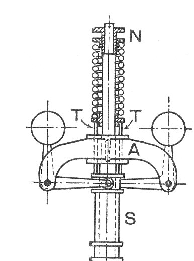
The weight rotate in a circle of diameter when the sleeve is in its mid-position and the weight arms are vertical. The equilibrium speed for this position is 450 r.p.m. neglecting friction. The maximum variation of speed (allowing for friction) is to be 5 % of the mid position speed. The weight of the sleeve is
and friction may be considered to be equivalent to 6 lb. at the sleeve. The power of the governor must be sufficient to overcome the friction by a 1% change of speed at the mid position.
Determine the weight of each rotating mass, the spring stiffness in lb./in and the intitial compression of the spring. (U.L.)
Example 8
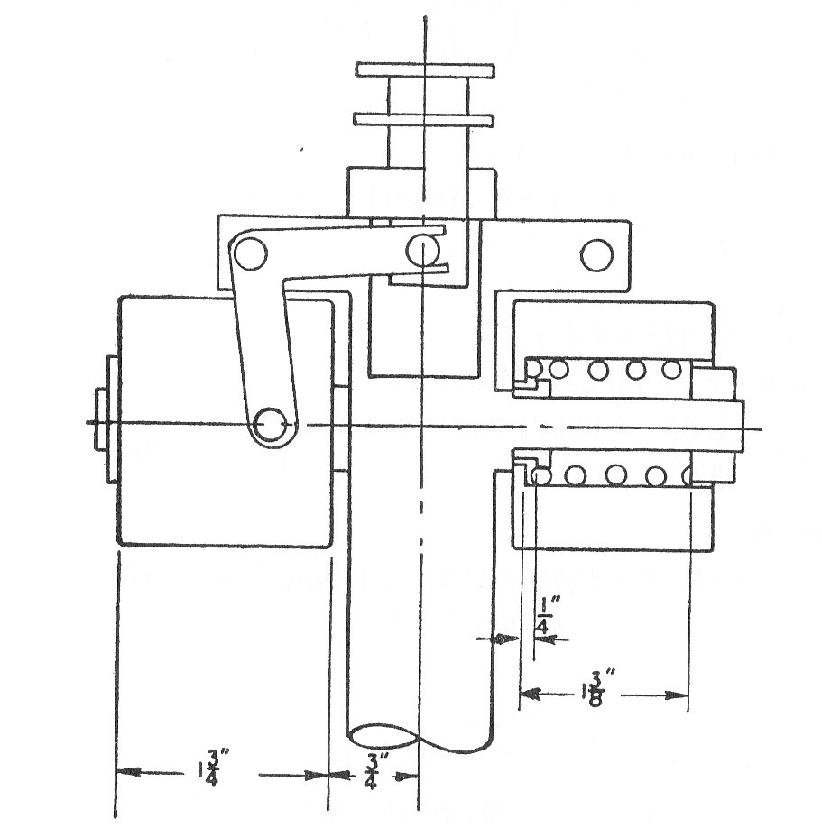
The diagram shows a centrifugal governor. Each of the two weights is 2.25 lb. and may be considered as a hollow cylinder 1.75 in. long, the other dimensions being as shown. Find the rate of the springs in lb./in. of compression and the uncompressed length if the sleeve is to commence to lift at 600 r.p.m. and reach its maximum displacement at 630 r.p.m.
If friction is found to be equivalent to a force of 3 lb. at the sleeve and if the ball and sleeve movements are equal, find the actual speed range.
Example 9
(a) Shaft governors may be of the centrifugal or of the inertia type. Distinguish between the actions of these two types in controlling the speed of an engine.
(b) A Shaft Inertia governor consists of an arm AB pivoted at C,C being a fixed point on a disc con
centric with and rigidly attached to the engine shaft. C is offset from the shaft axis O by 3 in. The Arm AB is 14 in.long and is symmetrical about C, that is AC=CB=7 in. A weight of 15 lb. is attached to each end of the arm at A and B, these weights being in the form of circular discs, each 6 in. in diameter, with their axes parallel to that of the shaft. In the normal position the arm ACB is at right angles to the radius OC
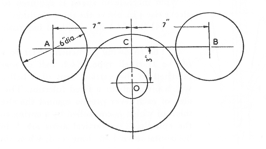
If the speed of the engine increases by 15 r.p.m. in 2 seconds, this increase being at a uniform rate, determine the torque needed to hold the arm stationary relative to the concentric disc. Neglecting the weight of the arms, explain carefully the reasoning behind any equations you may employ. (U.L.)
(a) The first part of this question has been discussed at the beginning of these pages.
(b)As the rate of increase in speed is uniform. Angular acceleration will be constant and Hence:-
Applying the formula about C, where I is the moment of inertia about C, which is also the centre of gravity of ACB