
Inertia Forces and Couples
Inertia is the resistance of any physical object to a change in its state of motion or rest, or the tendency of an object to resist any change in its motion. It is proportional to an object's mass.
Centre of gravity is the point in or near a body at which the gravitational potential energy of the body is equal to that of a single particle of the same mass located at that point and through which the resultant of the gravitational forces on the component particles of the body acts.
A force is any influence that causes a free body to undergo a change in speed, a change in direction, or a change in shape. Force can also be described by intuitive concepts such as a push or pull that can cause an object with mass to change its velocity, i.e., to accelerate, or which can cause a flexible object to deform.
Inertia Forces and Couples with particular reference to Reciprocating Engines
You're viewing an older version of this page (#3731). View the current version.
Introduction
This section on Inertia Forces and Couples should be read in conjunction with those covering Velocity and Acceleration. There you will find details of both velocity and acceleration diagrams and Klein'\b{s construction} and all these are used in the Worked Examples.
Inertia Forces
If the centre of gravity of a body of mass has a linear acceleration
, then the resultant of the external forces acting on the body must be
. It follows that the external forces would be in equilibrium with a force of
in the opposite direction.
This latter force is called The Inertia Force and it is numerically equal to the product of mass and acceleration of the centre of gravity. It acts in the opposite direction to the acceleration.
The system of external forces and inertia forces is treated as if in statical equilibrium. Note that the use of centrifugal force in Governor problems is a particular example of this principle.
Inertia Couples
If the angular acceleration of a body is , then in addition to the Inertia Force at the centre of gravity, there is an Inertia Couple
where
is the moment of Inertia about the centre of gravity. As above, the direction of the inertia couple is opposed to the angular acceleration.
- If the body is turning about a fixed axis
, then the inertia force and couple can be combined into a couple of magnitude
- The inertia force and couple may be reduced to a single force of magnitude
which acts in a parallel direction at a distance
Engine Mechanisms
Inertia of reciprocating parts
It was shown in " Velocity and Acceleration Equation(20)" that the acceleration of the piston is given by:
where is measure from the inner dead-centre position and the negative sign indicates that the acceleration is towards the crank. Thus if
is the mass of the reciprocating parts:
Inertia Force
and the effective force along the line of the crank is given by:
Where is the force of the gas on the piston and is towards the crank.
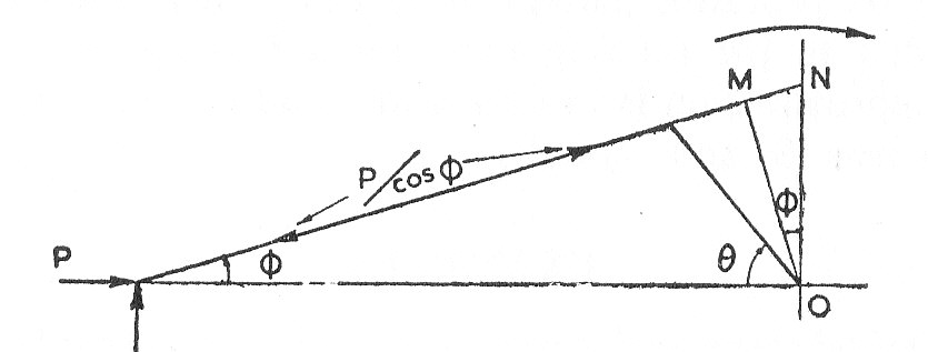
It can be seen from the diagram that is accompanied by a foirce in the connecting-rod of
and the useful turning moment on the crankshaft during the power or outstroke is:
On the instroke the turning moment in the direction of rotation is with the other senses remaining as before (See example 1)
The Inertia of the Connecting-rod.
The linear acceleration of the centre of gravity, , and the angular acceleration
can be found graphically by using the method described in "Velocity and Acceleration" or by Klien's construction. The Inertia Force and the Couple can then be calculated and reduced to a single force
at a distance
from the centre of gravity (See paragraph 2)
Assuming that the reaction at the small end is perpendicular to the line of stroke, the reaction at the big end and hence the turning moment on the crank due to the inertia of the connecting-rod can be determined (See example 3)
The Equivalent two-mass system
Any body of total mass can be replaced by dynamically by two "point" masses
and
at distances
and
respectively from the centre of gravity. The choice of the masses and there positions must satisfy the following conditions:
- (5)
- (6)
- ((7)
is the radius of gyration about
)
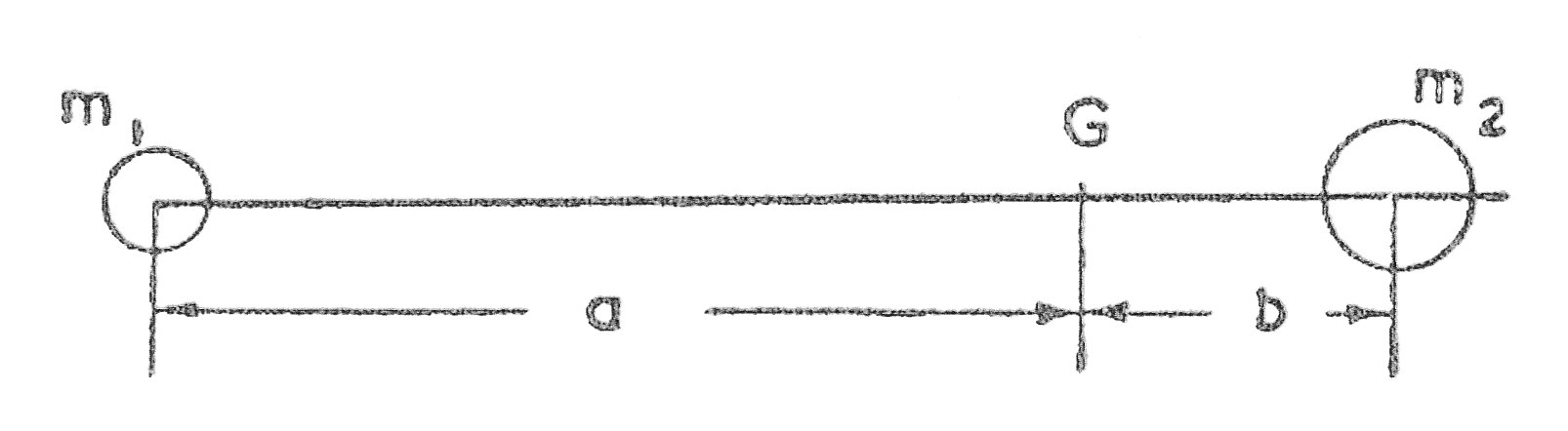
i.e. The new system has the same mass; the same position and the same moment of inertia as the original.
The method of solving these equations is either to :
- Fix one of the masses. This allows equations (#4) (#5) and (#6) to be solved and give:
- Fix
and
and calculate the two masses. This allows the calculation of
and
from equations (#4) and(#5) only.
In applying to a connecting-rod it is normal to fix and place it at the small end where it can be added to the reciprocating parts.
will lie near to the big end and may be added to the rotating parts for a first approximation.
Example 1 [imperial]
A horizontal steam engine running at 240 r.p.m. has a bore of 15 in. and a stroke of 30 in. The connecting rod is 52.5 in. long and the reciprocating parts weigh 120 lb. When the crank is at past its inner dead-centre, the steam pressure on the covered side of the piston is 90 p lb/sq.in. while that on the crank side is 10 lb/sq/in.
Neglecting the area of the piston rod, determine:
- a) The force in the piston rod.
- b) The turning moment on the crankshaft.
From the given dimensions ,
, and
- a) Using equation (3)
- b) This part of the question has a graphical solution.
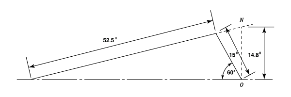
From the drawing
- a) The force in the piston rod is
- b) The turning moment on the crankshaft is
Example 2 [imperial]
A vertical internal combustion engine has a cylinder bore of 7 in. and a stroke of 8 in. The speed is 500 r.p.m., the connecting rod is 16 in. long and the weight of the parts moving with the piston is 45 lb. On the working stroke the gas pressure is 176 lb./sq.in. when the piston has moved downwards a distance corresponding to a rotation of of the crank.
Determine graphically the velocity and acceleration of the piston for this position. Find also the turning moment exerted on the crankshaft taking into account the weight and inertia of the piston.
For notes on velocity and acceleration diagrams see " Theory of Machines - Velocity and acceleration. Paragraphs 2 and 4"
In diagram (a) let be the instantaneous centre of the connecting-rod
. The velocity of the crank pin is then given by:
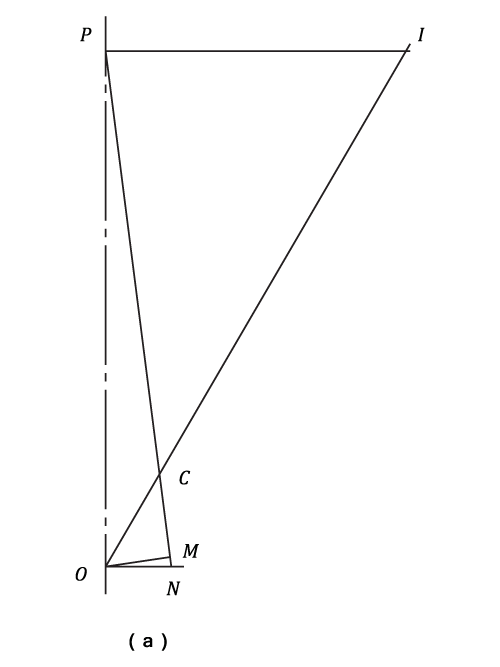
The angular velocity of is:
And the velocity of the piston =
Now from (b) the acceleration diagram:
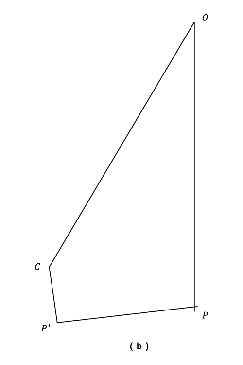
The acceleration of is given by:
And the centripetal acceleration of to
is:
Note. ' is the tangential component (perpendicular to
) and
is along the line of the stroke.
Piston Acceleration, downwards.
Piston Inertia Force = upwards.
The effective downwards force is the sum of the gas and weight forces less the inertia force.
i.e. The effective Downwards Force =
Using the principles of work:
Turning Moment Angular Velocity = Force
Linear velocity
Hence, Turning Moment =
Alternatively, the turning moment = the force in
(
is perpendicular to
)
- The turning moment is
Example 3 [imperial]
The single cylinder engine shown in the diagram, has a crank of 5 in. and a connecting-rod
of 20 in. long. The piston weights 60 lb. The connecting -rod weighs 40 lb. with a centre of gravity
6 in. from
and a radius of gyration about
of 8 in. The acceleration of
and that of
and the angular acceleration of the rod are shown for the position shown in the diagram.
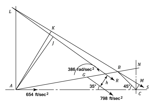
Find the turning moment which must be applied at the crankshaft to overcome the inertia of the piston. Find also the single force required for the acceleration of the rod and considering this as the resultant of the reactions at its two ends, find the corresponding turning moment at the crankshaft.
Piston inertia force =
From equation (4)
The turning moment on the crank =
is the single force required to accelerate the connecting-rod. Its magnitude is
i.e.992 lb. acting in the direction of acceleration and displaced a distance
from
such that:
Assuming that the reaction at due to the inertia of the connecting-rod, is perpendicular to the stroke, the reaction
at
must pass through
and so by taking moments about
.
The turning moment on the crank =
- The turning moment is
- The single force required is
- The corresponding turning moment is
Example 4 [imperial]
A connecting- rod is 4 ft.long and 3 in. in diameter which is assumed to be uniform throughout its length. The crank is 1 ft. long and the engine speed is 240 r.p.m.
Draw the inertia - load diagram for the connecting-rod when the crank is at from the inner dead-centre position. Determine the value of the maximum bending moment and state its position.
Klien's construction (See Theory of Machines Velocity and Acceleration)is used to find , the acceleration image of the connecting-rod.
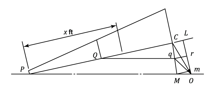
For any point on the rod, a line parallel to
is drawn to cut
in
is the acceleration of
. The component acceleration perpendicular to the rod is
which is found by projecting
onto
, which in itself perpendicular to
.
It can be seen from the construction that the value of varies uniformly from
(0.95 ft. to scale) at
to
(0.08) at
. The rate of inertia load will therefore vary from:
to
This loading is shown diagrammatically as a "trapezium" and may be broken down into a uniform rate of 37 lb./ft. throughout, together with a uniformly varying rate having a value of at
and 401 lb./ft.at
.
Treating as a "Beam" by taking moments about
the reaction at
is given by:
If x ft. is the distance of the point of maximum bending moment from then:
(i.e. the shearing force is zero)
from which and the maximum bending moment is :
- The value of the maximum bending moment is
Example 5 [imperial]
The connecting-rod for an internal combustion engine has a length between centres of 9 in. and a total weight of . Its centre of gravity is
from the small end and its radius of gyration about the centre of gravity (for oscillations in the plane of swing of the connecting-rod) is
. The weight of the piston and gudgeon pin is
; the stroke is
and the cylinder bore is 4 in.
Determine the magnitude and direction of the resultant force acting on the crank pin when the crank is at after the inner dead-centre and speed is 1,600 r.p.m.and if the effective gas pressure on the piston is 250 lb./sq.in.
Klien's construction produces the acceleration diagram OCLM shown in the diagram (a). (A description of Klein's construction will be found in " Theory of Machines - Velocity and Acceleration")
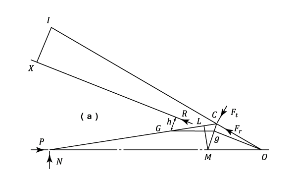
Piston acceleration =
The effective Force on the piston is given by (Compare this with equation (1))
For the connecting-rod the acceleration of is given by:
And the angular acceleration is given by:
The Inertia Force for the connecting-rod, , is given by:
In the reverse direction to the acceleration and acting at a distance :
Let the components of the reaction at the crank pin be and
. Then by moments about
:
The Force diagram can now be drawn
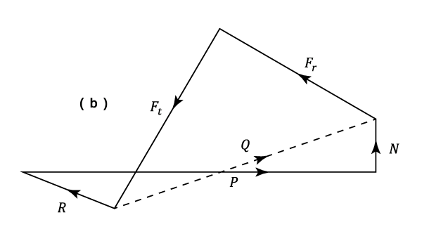
From the above diagram
And the Force on the crank pin is shown to be:
Example 6 [imperial]
A two cylinder vertical stem engine has cranks at right angles. The crank radius is 4 in. and the length of the connecting rod is 16 in. The reciprocating parts for each cylinder (i.e. Piston; piston rod; and crosshead ) weigh 50 lb. Each connecting-rod weighs 28 lb., the centre of gravity being 6 in. from the centre of the big end and the radius of gyration about an axis through the centre of gravity parallel to the crank shaft being . The rotating parts of the engine weigh 150 lb. with a radius of gyration of 7 in.
Calculate the total kinetic energy of the moving parts at the instant when one piston is at top dead centre, the speed then being 180 r.p.m.
Determine the error which would result from making the common assumption that one-third of the mass of the connecting-rod may be treated as being concentrated at the cross head pin and two thirds at the crank-pin.
- a) Exact Analysis
For the Crank on top dead centre. The velocity of the crank pin is given by:
At the same moment the velocity of the piston is zero and thus the instantaneous centre of the connecting rod is at the piston. Therefore the angular velocity of the connecting-rod is:
The velocity of the centre of gravity of the connecting-rod is:
NOTE The piston has NO velocity and the centre of gravity of the connecting rod has both linear and angular velocity. Hence the Kinetic Energy of the piston and connecting-rod is:
- Now considering the other cylinder. The Crank is at
. The velocity of the crank pin for this cylinder is equal to the velocity of the piston. i.e. The Instantaneous Centre of the connecting-rod is at infinity and the angular velocity of its centre of gravity is zero.
Hence the Kinetic Energy is given by:
- The Kinetic Energy of the moving parts is:
Total Kinetic Energy =
- b) Approximate Analysis
- For the piston with crank at top dead centre, the Kinetic Energy becomes:
- For the piston with crank at
- The Kinetic Energy of the rotating parts remains the same.
- The Total Kinetic Energy is now:
- c) The error
The Error =
- The error is