
Turning Moment Diagrams
A flywheel is a mechanical device with a significant moment of inertia used as a storage device for rotational energy.
A diameter of a circle is any straight line segment that passes through the center of the circle and whose endpoints are on the circle. The diameters are the longest chords of the circle.
Turning Moment Diagrams with particular reference to Engines and Flywheels.
You're viewing an older version of this page (#3910). View the current version.
Introduction
In any machine there is at least one point where energy is supplied, and at least one other point from which energy is delivered. In an ideal machine no energy would be lost and these two would be equal. In practice this state of affairs does not exist since it is inevitable that some energy is absorbed in over coming friction at the various joints, couplings and bearings.
The ratio of energy out to energy in is known as the Mechanical Efficiency of the machine.
In addition, over a given interval of time, the kinetic and potential energies of each link will change so that either some of the energy supplied will be absorbed increasing the total energy (Kinetic and potential) of the moving parts, or alternatively the energy supplied will be supplemented by a decrease in the total energy of the moving parts.
It should be stressed that over the time taken for the machine to complete one cycle, the net change of energy for each moving part is nil, since at the end of the cycle each part is in the same position and has the same speed as at the beginning of the cycle. However, during the cycle the input of energy or the load on the machine may vary considerably. In most cases this fluctuation is kept to a minimum by the use of a flywheel.
Fluctuations of Energy and Speed
The driving torque produced by a reciprocating engine fluctuates during any one cycle. The manner in which it varies depends upon the type of engine, number of cylinders, the characteristics of the flywheel etc. It can usually be assumed that the resisting torque due to the load
is constant, and when
>
the engine will be accelerating; and vice versa.
If there are complete cycles per minute and the engine speed is
Then the power transmitted is
i.e. = The mean height of the turning moment diagram
For any period during which the area cut off on the turning moment diagram represents "excess energy"
, which will go to increase the speed of the rotating parts.
where is the moment of inertia of the flywheel and rotating parts and
and
are the maximum and minimum speeds during one cycle.
Thus,
This can be re-written to include the mean speed as:
(Approximately)
The coefficient of fluctuation of speed is:
This is usually expressed as a percentage variation from the mean. i.e.
In simple cases is given by the area of one "loop" intercepted between
and
, but for multi-cylinder engines a further analysis is necessary. (See Example 5)
Disc and Rim Flywheels
The purpose of a flywheel is to absorb energy when the supply of energy to a machine exceeds the requirement, and to provide energy when there is a deficit.
A body when it rotates behaves as if all of its mass were concentrated in a ring at a distance from the axis of rotation. The radius
is known as the Radius of Gyration of the body. The product
is known as the Moment of Inertia of the body and given the symbol
.
For a solid disc of diameter ,
For a ring or rim of diameters and
,
Example 1 [imperial]
The mean speed of an engine is 250 r.p.m. The maximum fluctuation of energy generated in the engine is 850 ft.lb. and the resisting torque is constant. Determine the moment of inertia of the flywheel required to keep the speed within the range 1% above to 1% below the mean speed. State clearly the units in which the moment of inertia is expressed.
It is desired to reduce the coefficient of speed fluctuation by one fifth by bolting a plain cast-iron ring to the side of the flywheel. The ring is to have an outside diameter of 3ft. 4in. and an inside diameter of 2ft. 8in. and to be made of material which weighs 0.28 lb./cu.in. Find the width of the required ring.
The coefficient of fluctuation of speed and from equation (1)
Note. For those of you who are not used to the foot slug second system of engineering quantities, a full description can be found on the Codecogs site under References: Engineering: General. However in brief the Slug is that mass which on this planet weighs one pound (lb.)
To reduce the coefficient of speed fluctuation by one-fifth it is necessary to increase by one-quarter. As this is to be done by adding a ring of thickness
:
Note. is now measured in lb.in.^2 and the density of the flywheel material has been converted into slugs/cu.in. since the equation demands the mass of the flywheel rather than its weight.
- The moment of inertia is
- The width is
Example 2 [imperial]
The variation in turning moment with crank angle for a six-cylinder engine is shown in the diagram (a). The flywheel is equivalent to a mass of 32 lb. concentrated at a radius of 1 ft. and the mean speed of rotation is 1200 r.p.m. Sketch the speed crank-angle curve over a revolution and estimate the difference between the maximum and minimum speeds.
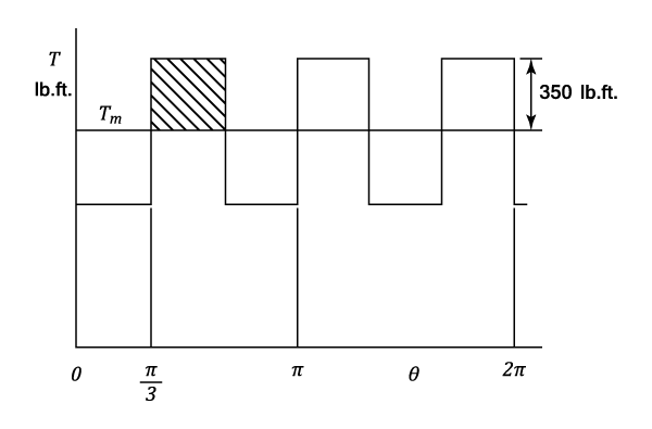
If the crank-angle base can now be assumed to be a time base and also the speed changes to be linear with time, estimate the angle through which the crank advances and falls back relative to an imaginary crank rotating uniformly at the mean speed.
- The speed is increasing when the turning moment is above the mean and decreasing when below the mean.
- The maximum velocity occurs at the end of a period of excess turning moment and the minimum velocity is at the end of a period of minimum turning moment.
- The variation in speed with crank angle is shown in diagram (b) and is a series of straight lines. This is because the turning moment is constant in each interval.
The gain in Kinetic Energy = The excess work done
i.e.= The shaded area in diagram (a)
Or
From which
The crank is advancing whilst its speed is greater than the mean and its total angle of advance is represented by the shaded area in diagram (b) converted to a time base.
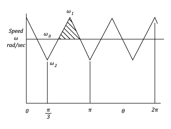
The height of the triangle =
The base of the triangle = Of a revolution
Which converted to a time base represents
The area of the triangle represents
- The area of the triangle represents
Example 3 [imperial]
A machine runs at a mean speed of 300 r.p.m. The torque required by the machine increases uniformly from 500 lb.ft. to 2000 lb.ft. whilst the shaft turns through , remains constant for the next
, decreases uniformly to 500 lb.ft for the next
and then remains constant for the next
. This cycle is repeated during each revolution. The power is supplied by a constant torque motor and the fluctuation in speed is to be limited to
of the mean speed.
Find:
- a) The horse power of the motor.
- b) The moment of inertia of a suitable flywheel to be fitted to the machine shaft.
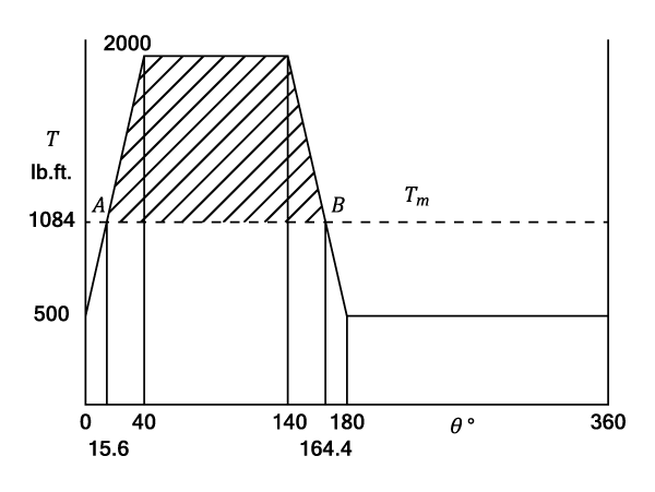
The mean torque = The area under the graph / The base
The horse-power of the motor equals:
The position on the graph can be found by proportions and equals:
The angular rotation from position to
is:
The shaded area = The loss of kinetic energy
Or where
is the mean speed
From which,
(Note:
)
- a) The horse power of the motor is
- b) The moment of inertia is
Example 4 [imperial]
An engine has three single-acting cylinders, the cranks are spaced at to each other. The crank effort diagram for each cylinder consists of a triangle having the following values

Find:
- a) The mean torque
- b) The moment of inertia of the flywheel in
to keep the speed within
The combined turning moment diagram is shown by the full line on the following diagram and is the sum of the torques given by the three separate triangles (Broken lines). Where the triangles overlap, the combined torque is the sum of the two separate values and will follow a linear variation between values of 75 lb.ft. and 150 lb.ft.
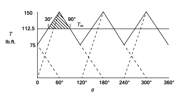
- a) The Total Work done per revolution
- b) It can easily be seen that the men torque line is three-quarters of the maximum height and that it cuts the combined diagram at
and hence
Using equation (1)
- a) The mean torque is
- b) The moment of inertia is
Example 5 [imperial]
The turning moment diagram for a multi-cylinder engine has been drawn to a scale of 1 to 5000 lb.ft. vertically and 1 in. to horizontally, the intercepted areas between the output torque curve and the mean resistance line, taken in order from one end are :- -0.52, +1.24, -0.92, +1.4, -0.85, +0.72, -1.07 sq.in. when the engine is running at 800 r.p.m.
If the weight of the flywheel is 1200 lb. and the total fluctuation from the maximum to minimum speed does not exceed 2% of the mean speed, what is the minimum value of the radius of gyration.
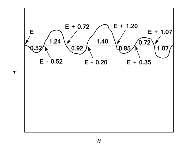
It is necessary to determine the maximum and minimum energy values during the cycle. If is the total energy at the beginning of the cycle, then the values at the end of each loop are as follows:
and
.
From which it can be seen that the maximum overall fluctuation of energy is given by:
Allowing for the scale factor:
Using equation (1),
But and
Thus or
- The radius of gyration is
or