Balancing of Inertia Forces
The Balancing of Inetia Forces with particular referance to Engines; Air Compresssors and Steam Locomotives.
You're viewing an older version of this page (#3561). View the current version.
Introduction
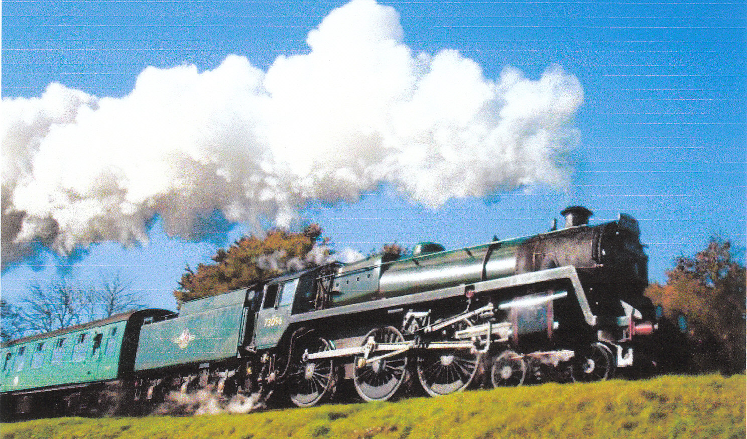
The high speeds of rotation at which modern machines and engines are required to operate, has made it increasingly important that all revolving and reciprocating parts are as completely balanced as possible. Not only are the bearing loads and stresses in components increased by out of balance dynamic forces but there is also the possibility of causing significant harmful vibrations. On the railways these were called "Hammer Blows" and they were reduced by casting Balancing weights into the driving wheels. These can be clearly seen in the photograph at the bottom of the wheels
On road transport wheels are routinely balanced by adding small weighs around the rim. These improve wheel bearing life but more importantly prevent vibrations being set up in the steering system which are at best unpleasant and at worst very dangerous.
It would be wrong to assume that all vibrations caused by out-of balance forces are undesirable since they are used to agitate liquids or to prevent granular solids for "sticking".
Rotating Masses in one Plane
When a mass M, which is attached at a radius r to a shaft, is rotated with an angular velocity , there is an outwards radial force of
. which will produce a bending moment in the shaft. To counteract the effects of this inertia force ,a balance weight may be
introduced into the plane of rotation of the original mass such that the inertia forces of the two masses are equal.
If W is the weight of the balancing mass and b its radius of rotation. Then:-
Note:- It is normal to make b as large as possible since this reduces the value of W
If a system of several rotating masses, attached to the same shaft, the effect is equivalent to a set of concurrent forces. Since is the same for all the masses attached to one shaft, the centrifugal forces are proportional to M r (or W r) and the problem can be solved graphically by means of a polygon of forces or analytically by resolving in two directions.
If the masses are to be balanced, the polygon must close. If it does not close the "gap" is the measure of the out-of-balance force on the shaft. Note that the polygon can be drawn for any particular angular position of the shaft carrying the masses and will rotate as a whole with the shaft.
Rotating Masses in Parallel Planes
Again each mass exerts an outwards centrifugal force proportional to M r > The forces are equivalent to a set of exactly similar forces in one chosen plane ( The reference Plane) together with a set of couples proportional to M r x where x is the distance from the plane of M to the reference plane. It is necessary to reckon positive to one side of the reference plane and negative to the other.
The forces("M r") are balanced as before by drawing a force polygon. This tests for Static Balance. Similarly the couples can be represented by vectors drawn in the radial direction and can be balanced by drawing a Couple Polygon ("M r x"). Negative couples are drawn in the radially inwards direction. If the polygon closes, then the system is in dynamic balance. If it does not close,then the gap represents the out-of balance moment about the reference plane.
Note. It is only a pure couple if there is no out-of-balance force. Static balance can be obtained without dynamic balance but the reverse is not true see Example 3
Reciprocating Masses
The Inertia Force of a rotating mass M is
(See Inertia Forces and Couples equation (3) and "Velocity and Acceleration Equation (20))
This force is provided by the pull of the connecting-rod and with reference to the following diagram:-
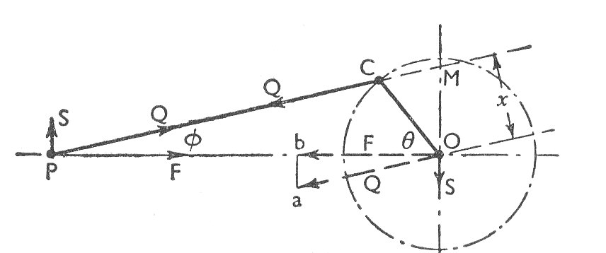
- The connecting-rod is in tension and the force Q applied by the rod to the crank pin C is equivalent to an equal and parallel force through O together with a couple Q.x.
- The Couple Q.x tends to retard the rotation of the crankshaft and its effect is taken into account when finding the net turning moment on the crankshaft.
- The force at O is transmitted from the crankshaft through the main bearings and onto the engine frame.
- Both the force at O and that at P may be resolved parallel and perpendicular to the line of stroke. The horizontal components are equal and opposite.
- The one acting through P accelerates the reciprocating parts
- The other through O is an unbalanced force applied to the frame and this causes the frame to slide backwards and forwards on its mountings as the crank rotates
- The two vertical components are equal and opposite and constitute a couple applied to the frame which attempts to rotate the frame in a clockwise sense.
As the triangles Oba and POM are similar:-
The full effect on the engine frame of the inertia of the reciprocating mass is equivalent to a force F along the line of stroke at O and to the clockwise couple of magnitude S.OP
The Inertia Force can be separated into two parts:-
is called The Primary Force.
which is called The Secondary Force
It is clear that the primary force is equivalent to the component along the line of stroke of the centrifugal force due to an equal mass M rotating with the crank and at crank radius. Consequently, in the case of a single-cylinder engine, the primary reciprocating force could be balanced by a rotating mass on the other side of the crank pin. However this would introduce an unbalanced component of the centrifugal force of magnitude perpendicular to the line of stroke. A compromise solution (partial balance) is usually applied, the inertia force being reduced to a minimum when 50% of the reciprocating mass is balanced.
The secondary force is similarly equivalent to the component of the centrifugal force of mass M at radius r/4n rotating at being coincident with the crank at inner dead-centre.
Multi-cylinder In-line Engines
The usual arrangement for multi-cylinder engines is to have the cylinder centre line all in the same plane and on the same side of the crankshaft centre line. This constitures an "In-line" engine. Notable exceptions to this rule are "Vee" engines in which there are in effect two banks of in-line cylinders and "Flat" engines in which half the cylinders are arranged on opposite sides of the crankshaft.
Assuming that and n are the same for all cranks, they can be omitted from all considerations of engine balance but they must be included when actual values are required.
(a) Primary Balance
For couples and forces to be in balance:-
And
The equations can be solved analytically or by polygons drawn in the relative crank directions. This is similar to those used for rotating balance.
Any gap remaining in the force or couple polygons represents ( to a certain scale) the maximum out-of-balance value. This occurs twice per revolution of the crank-shaft when its direction lies along the line of stroke.
(b) Secondary Balance
For complete balance:-
And
To solve graphically it is only necessary to draw vectors in the directions (i.e. relative to any one crank taken as zero) and repeat af for primary balance.
The Partial Balance of Two-cylinder Locomatives
It is normal for the cranks to be at right angles and as a result the secondary forces are small and in opposite directions. As a result they are usually neglected and only the primary forces and couples are considered.
It is usual to balance about two-thirds of the reciprocating parts with masses fixed to the wheels. The unbalanced vertical components of the reciprocating masses give rise to a variation of rail pressure known as Hammer Blow and a Rocking Couple about a fore and aft horizontal axis.
The unbalanced reciprocating masses cause a variation in draw-bar pull and a swaying couple about a vertical axis ( See examples 12 and 13)
Radial Engines - Direct and Reverse Cranks
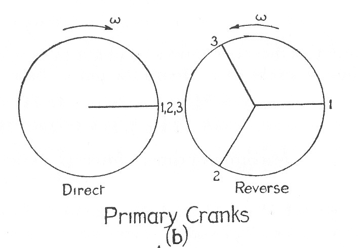
The primary force for a reciprocating mass M is equivalent to the resultant of the centrifugal forces of two masses M/2 rotating at a crank radius r and at a speed , one in the forward direction of motion and the other in the reverse direction. Note that the "direct" and "reverse" cranks are equally inclined to the dead centre position,
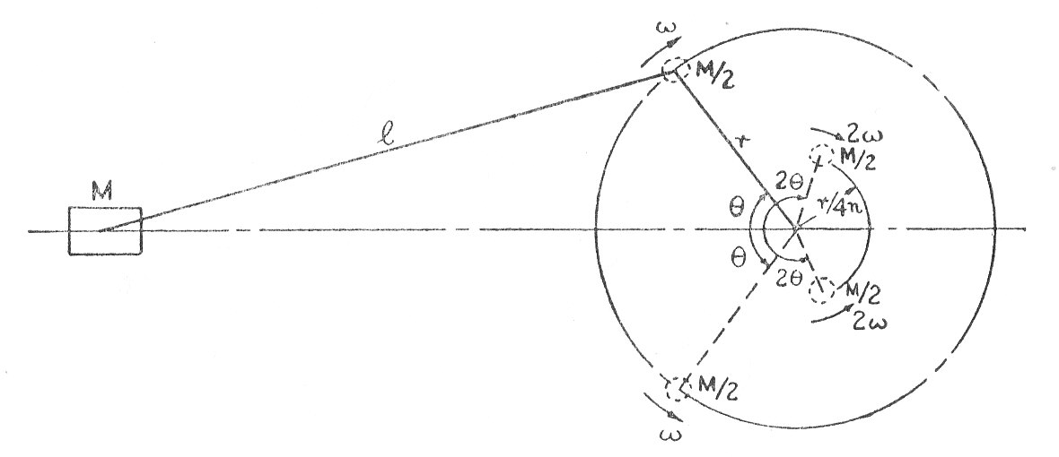
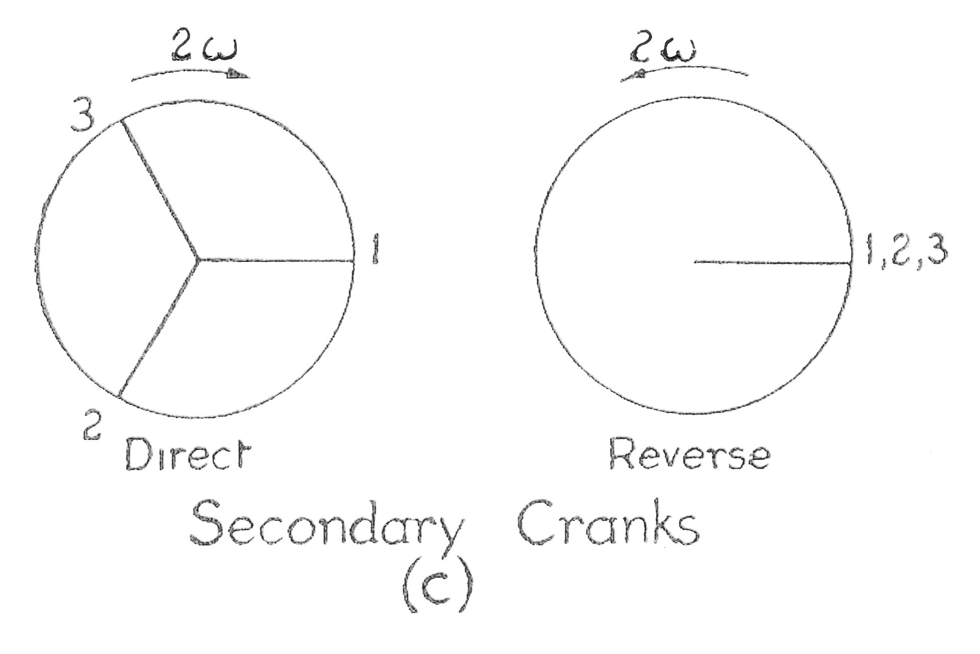
Similarly the secondary force can be represented by direct and reverse cranks inclined at to the inner dead centre and each carrying a mass M/2 at a radius r/4n rotating at a speed of
.
This method is particularly useful for examining the balance of radial engines with a number of connecting rods attached to the same crank. It is usually assumed that the crank and connecting rod lengths are the same for each cylinder, though from a practical consideration of design this is not generally true. (see Example 11)
Worked Examples
Please click the button to see the workings
Example 1
A motor armature is in running balance when weights of 0.130 oz. and 0.075 oz. ( There are 16 oz. in 1 lb.) are added temporarily in the positions shown in the planes A and D in the diagram
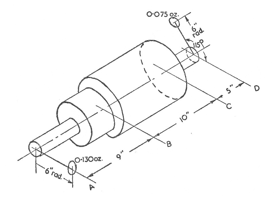
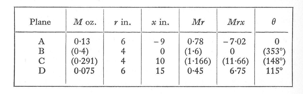
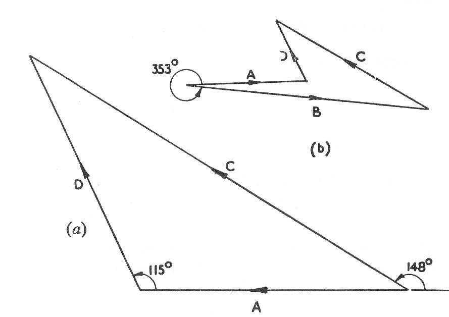
If the actual balancing is to be carried out by the permanent addition of masses in the planes B and C each at 4 in radius, find their respective magnitudes and angular positions to the radius shown in plane A.
Example 2
A shaft 5 ft.long is supported in bearings 6 in. from each end and carries three pulleys, one at each end and one at the mid point. The three pulleys are out of balance to the extent of 6, 9, and 8 lb.in, but are keyed to the shaft so as to give static balance.
Find (a) The relative angular settings of the three pulleys.
(b) The dynamic load on each bearing when the shaft makes 360 r.p.m.
Example 3
A shaft turning at a uniform speed carries two uniform discs A and B of mass 10 lb. and 8 lb. respectively. The mass centres of the discs are each 0.1 in. from the axis of rotation. The radii to the mass centres are at right angles. The shaft is carried in bearings C and D between A and B such that AC = 1 ft. AD = 3 ft. AB = 4 ft.
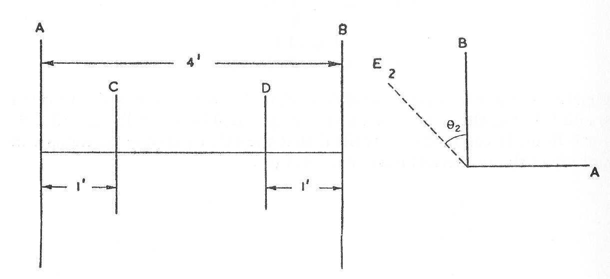
It is required to make the dynamic loading on the bearings equal and a minimum for any shaft speed by adding a mass at a radius of 1 in. in a plane E.
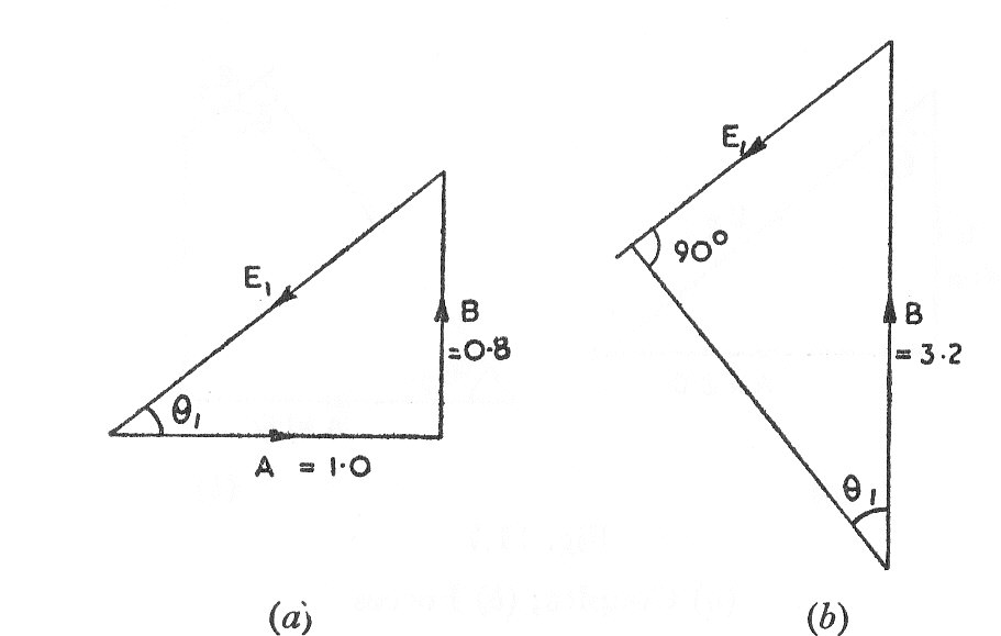
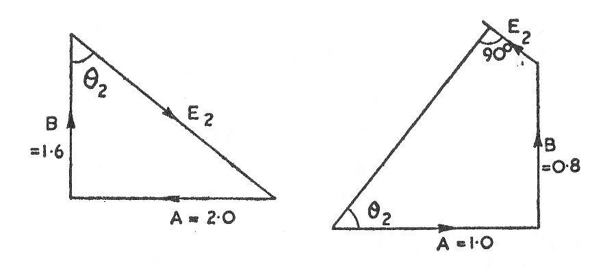
Determine (a) The magnitude of the mass in plane E and its angular position relative to the radial through the mass centre in plane A.
(b) The distance of plane E from plane A.
(c) The dynamic loading on each bearing when the mass in plane E has been attached to the shaft which is turning at 200 r.p.m. (U.L.)
Example 4
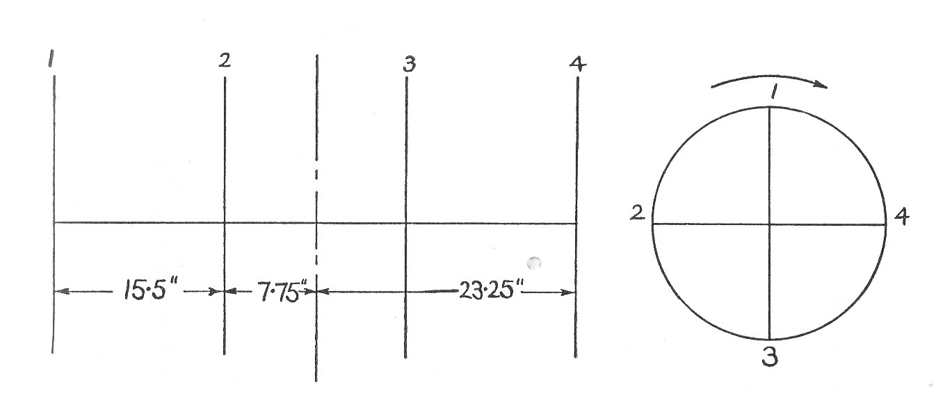
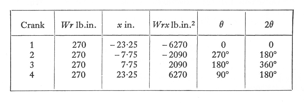
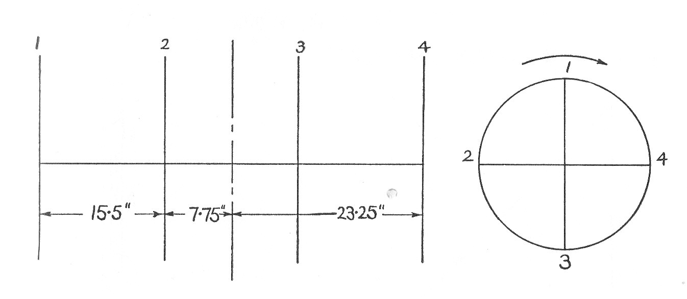
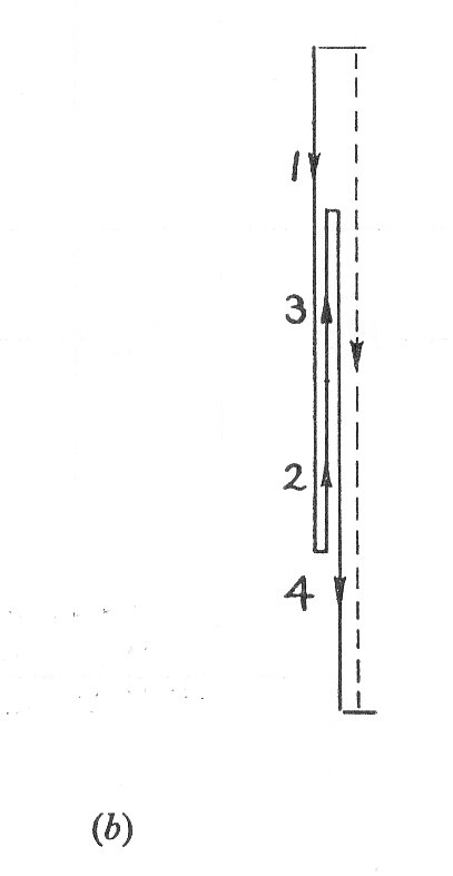
An air compressor has four vertical cylinders 1, 2, 3, 4, in line and the driving cranks, at intervals, reach their uppermost positions in this order. The cranks are 6 in. radius, the connecting rods 20 in. long, and the cylinder centre lines
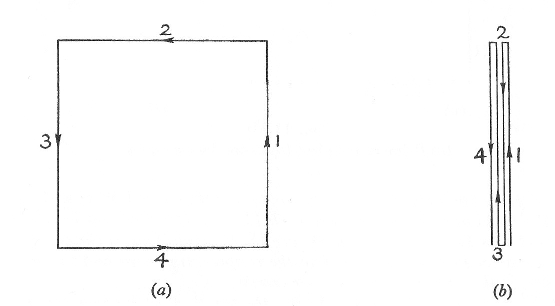
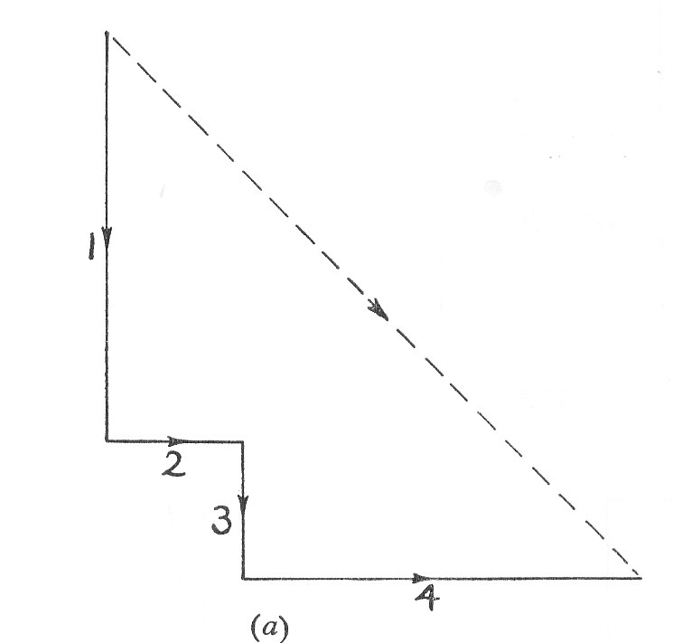
apart. The reciprocating parts of each for each cylinder weigh 45 lb. and the speed of rotation is 400 r.p.m. Show that there are no out-of-balance primary or secondary forces and determine the corresponding couples indicating the position of No.1 crank for maximum values. The central plane of the machine may be taken as the reference plane.
Example 5
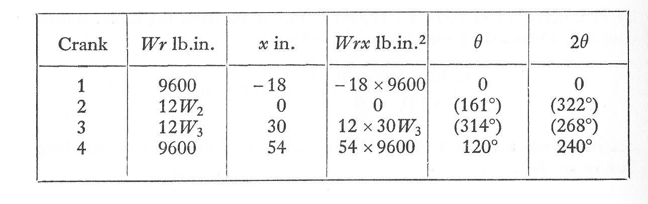
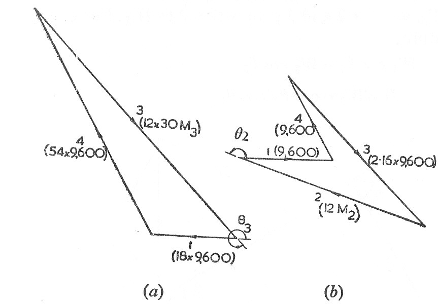
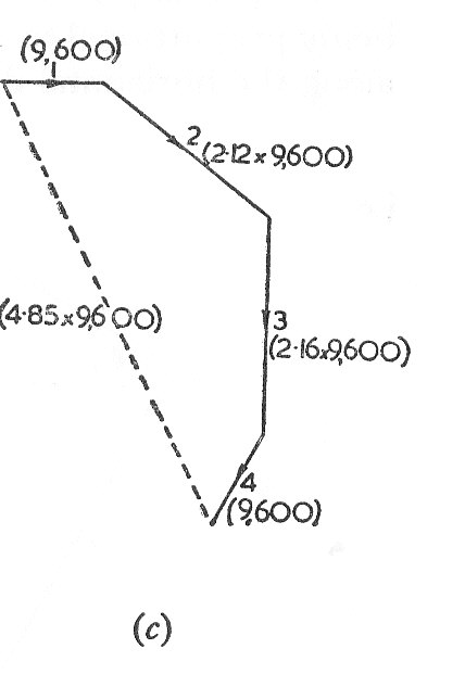
A four-crank engine has the two outer cranks set at to each other and their reciprocating masses are each 800 lb. The distances between the planes of rotation of adjacent cranks are 18, 30, and 24 in. If the engine is to be in complete primary balance, find the reciprocating mass and the relative angular position for each of the inner cranks.
If the length of each crank is 12 in., the length of the connecting-rods 48 in. and the speed of rotation 240 r.p.m., what is the maximum secondary unbalanced force?
Example 6
The diagram shows the arrangement of the cranks in a four-crank symmetrical engine in which the weights of the reciprocating parts at cranks 1 and 4 are each equal to and at cranks 2 and 3 are each equal to
.
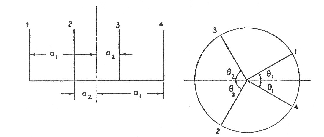
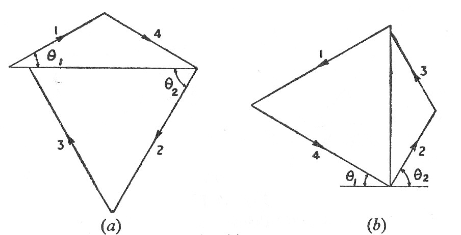
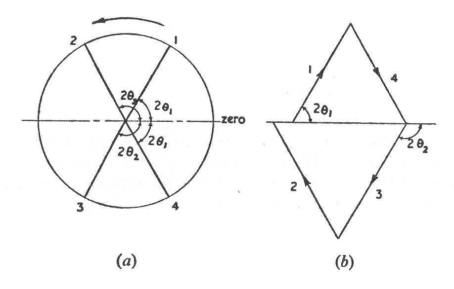
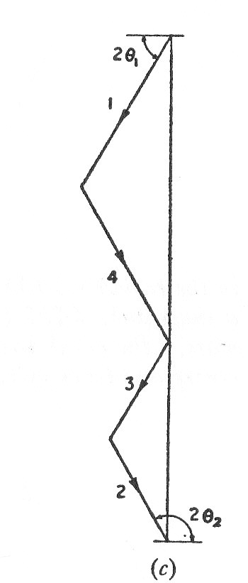
Show that the arrangement is balanced for primary forces and couples and for secondary forces provided that:-
Find also the value of the out-of-balance secondary couple when the system rotates at
Example 7
The five cylinders of a vertical in-line engine are similar in detail and symmetrical about the central one. The crank settings are as shown in the diagram.
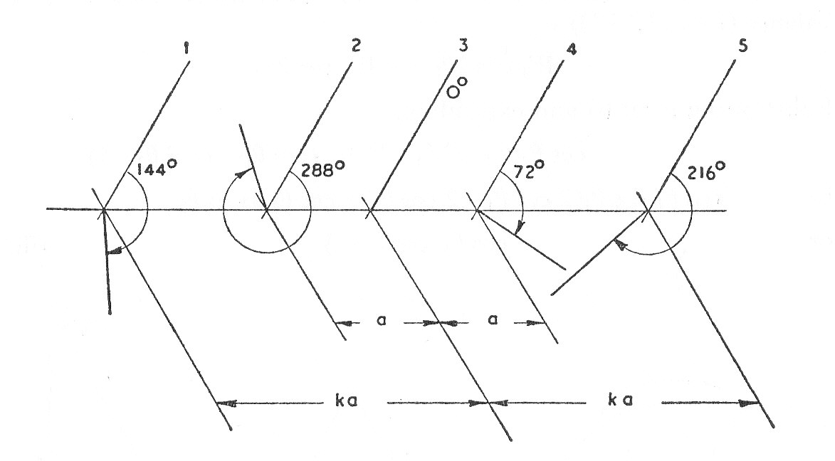
By sketching suitable vector diagrams verify that the engine is in balance for primary and secondary forces.
Show in a similar manner that the engine is in balance for primary couples if the distances of the outer and inner cylinders from the central cylinder are in the ratio and that the out-of-balance secondary couple then has the following magnitude :-
Where W is the weight of each reciprocating mass; l is the connecting-rod length; a is the distance between the central and inner cylinders and the speed of the engine.
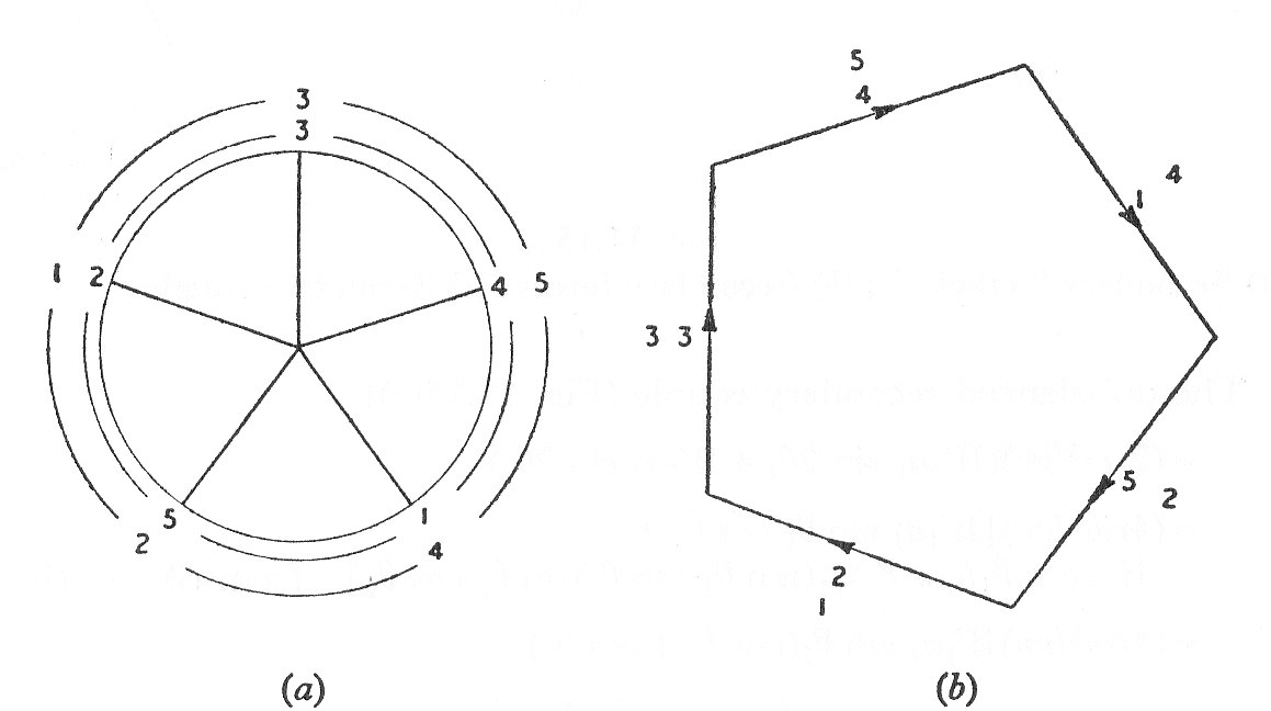
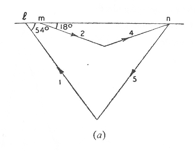
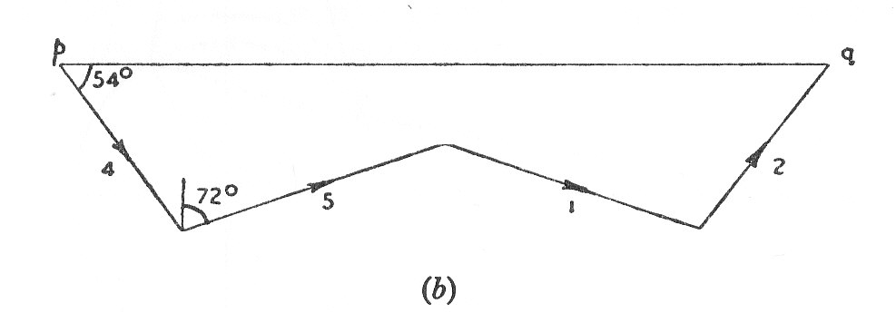
Example 8
A waterworks pumping engine has two cranks at right angles, radius 2 ft. in planes 10 ft. apart. Each crank has two connecting rods attached to it, one driven from a vertical high pressure cylinder in tandem with a pumping cylinder, the total reciprocating mass being 10,000 lb. and the other from a horizontal low pressure cylinder in tandem with another pumping cylinder. The total reciprocating mass of this is 12,000 lb. The engine runs at 30 r.p.m.
Find in terms of the angle made by the leading crank with the vertical, expressions for the vertical and horizontal components of the primary inertia forces and of the couples referred to the central plane. Hence calculate the maximum values of the resultant primary force and couple. (U.L.)
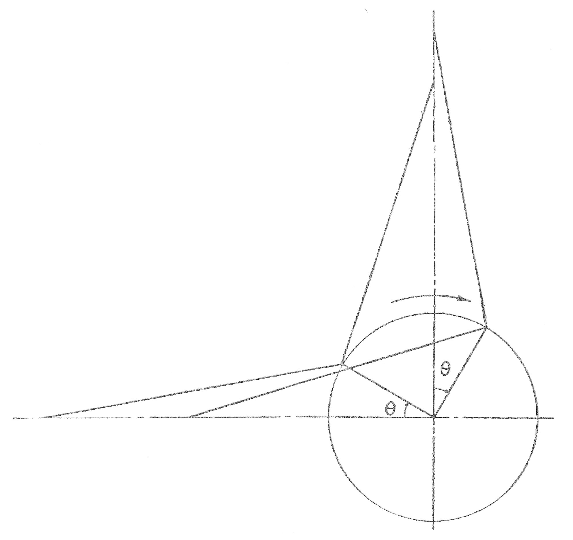
Example 9
a Vee-twin engine has a cylinder axes at right angles and the connecting-rods operate a common crank.
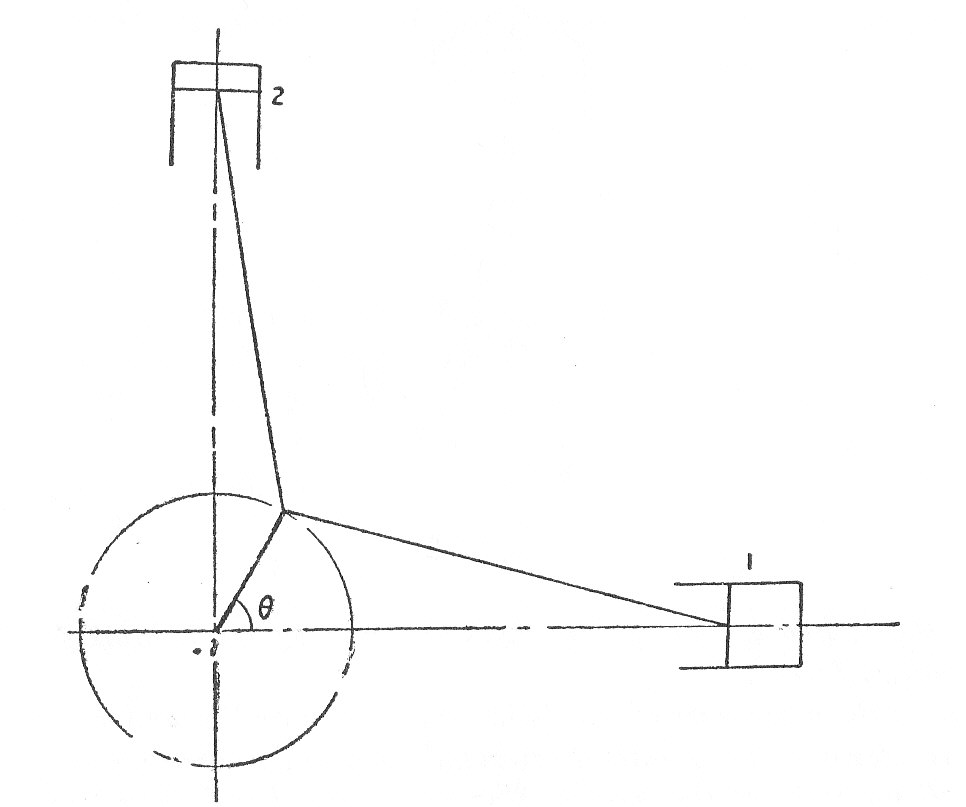
The reciprocating mass per cylinder is 25 lb.,the crank is 3 in. long and the connecting rods are 14 in. Show that the engine may be balanced for primary effects by means of a revolving balance weight.
If the speed is 500 r.p.m., what is the maximum value of the resultant second force and in which direction does it act.
Example 10
An internal combustion engine is arranged with three cylinders opening into a common combustion chamber as shown in the diagram. The centre lines of the cylinders are spaced at to one another. The reciprocating mass per cylinder is 4.6 lb., the piston stroke is 3.5 in. and the connecting-rods are 6 in. long.
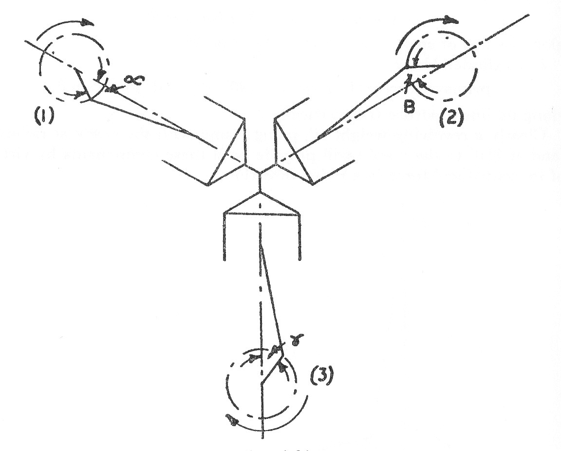
Show that when , the engine is in complete balance for both primary and secondary forces.
Calculate the maximum out-of-balance primary and secondary forces when crank 3 is advanced relative to cranks 1 and 2 so that
for all positions of the cranks. The engine speed is 1200 r.p.m. (U.L.)
Example 11
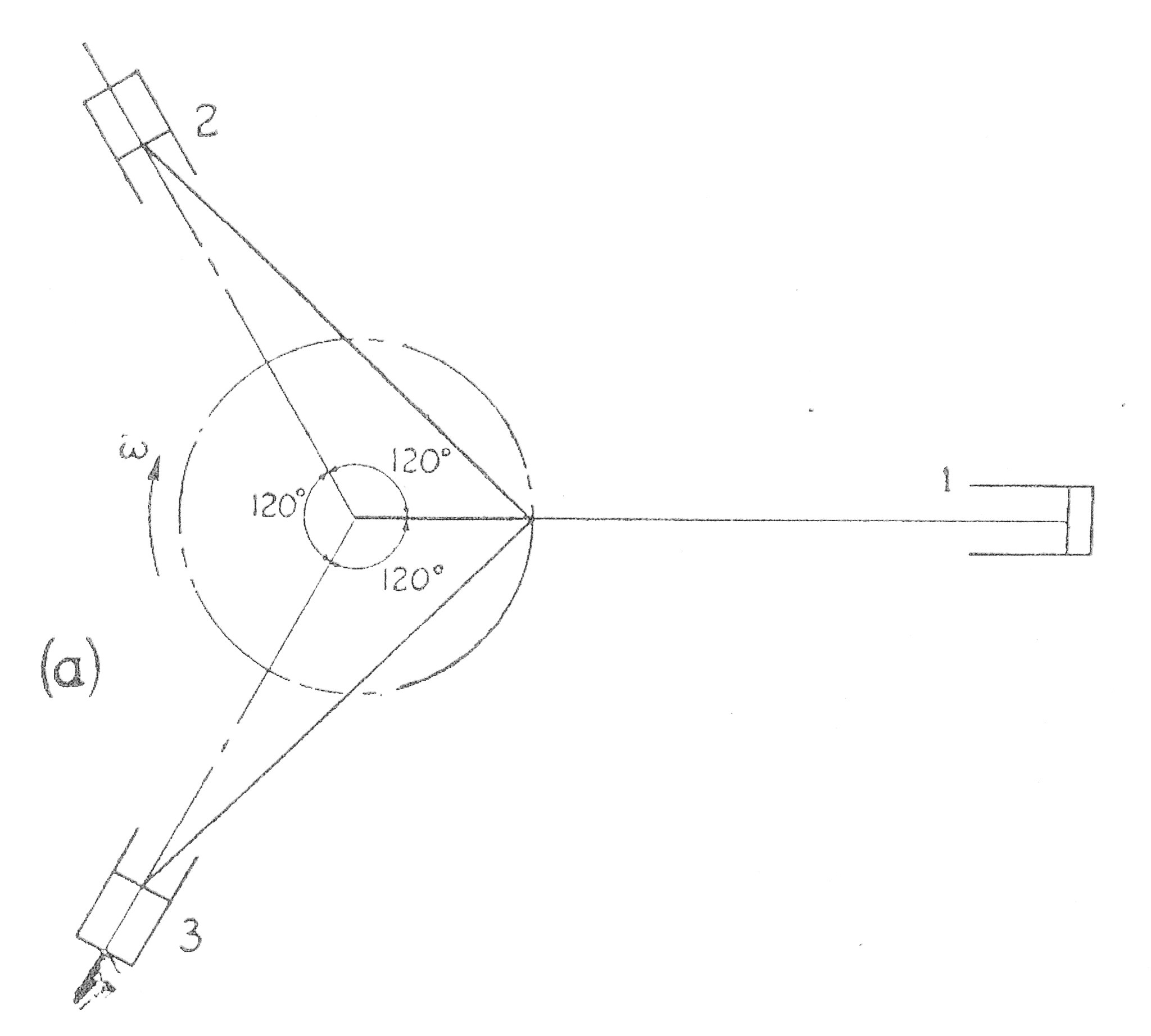
The three cylinders of an air compressor have their axes at to one another and their connecting rods are connected to a single crank. The stroke is 4 in., the length of each connecting-rod is 6 in. and the weight of the reciprocating parts per cylinder is 3.75 lb.
From first principles find the maximum primary and secondary forces acting on the frame of the compressor when it is running at 3000 r.p.m.. Describe clearly a method where by such forces may be balanced. (U.L.)
The method of direct and reverse cranks will be used. See paragraph 7
Example 12
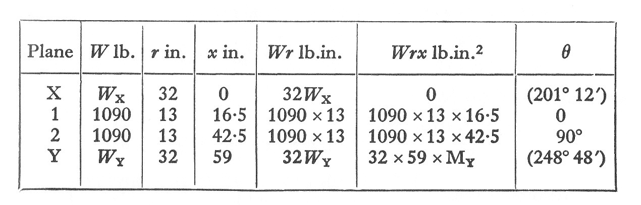
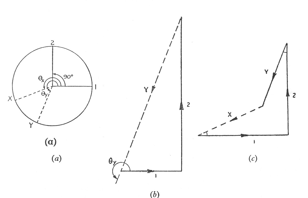
The following particulars refer to an inside-cylinder locomotive. The reciprocating mass per cylinder is 550 lb., the rotating mass per cylinder is 650 lb., the cranks have a 13 in. radius at , the cylinder centre are 26 in., and there are balance weights in the wheels at 32 in. radius in planes which are 59 in. apart.
Determine the size and angular position of the balance weights so that the inertia forces due to the rotating and 0.8 of the reciprocating parts are balanced. For this condition, and when the wheels are making 5 r.p.s. determine with reference to the central plane of the engine, the magnitude of the unbalanced moments about horizontal and vertical axes.
Example 13
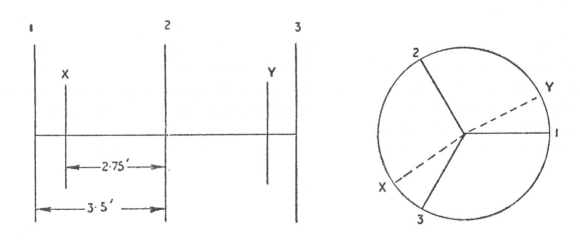
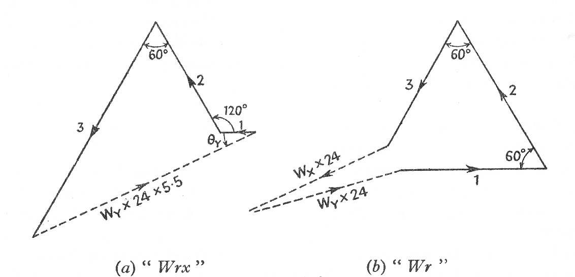
The three cranks of a three cylinder locomotive are all on the same axle and are set at . The pitch of the cylinders is 3.5 ft. and the stroke of each piston is 26 in. The reciprocating masses are 600 lb. for the inside cylinder and 520 lb. for each of the outside cylinders and the plane of rotation of the balance weights are 2.75 ft, from the inside crank.
If 40% of the reciprocating parts are to be balanced find:-
(a) The magnitude and position of the balance weights required at a radius of 24 in.
(b) The "Hammer Blow" per wheel when the axle makes 6 r.p.s.