
Pipe Head Loss
The flow through pipes allowing for frictional and other losses. Includes the proofs of the Bernoulli Equation; Darcy's Equation; Reynolds number; The Chezy Formula and the Poiseuille Equation for laminar flow
You're viewing an older version of this page (#3568). View the current version.
Introduction
In general the flow of liquid along a pipe can be determined by the use of The Bernoulli Equation and the Continuity Equation. The former is an algebraic expression of the conservation of energy and the latter is a statement that what goes into one end of a pipe, comes out at the other end! It must be stressed that in this paper only Incompressible liquids are being considered.`
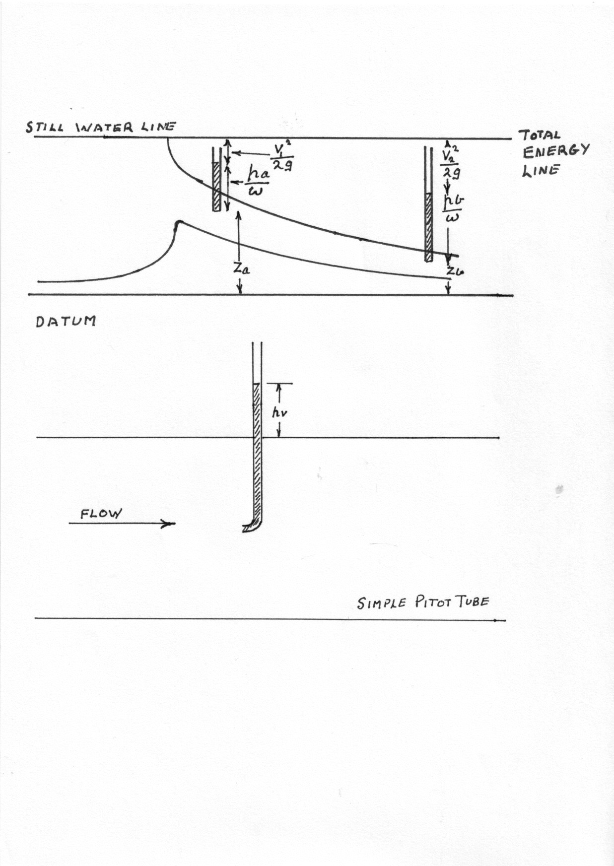
Bernoulli's Equation
This is usually expressed as:-
Where is the head lost due to friction.
Proof
The proof of the above equation has been hidden. It can be seen by clicking the button
Head Losses
These can be considered under two headings. The first is frictional losses within the pipe and the second covers bends; valves; sudden enlargements etc where turbulence is set up within fluid and this leads to losses.
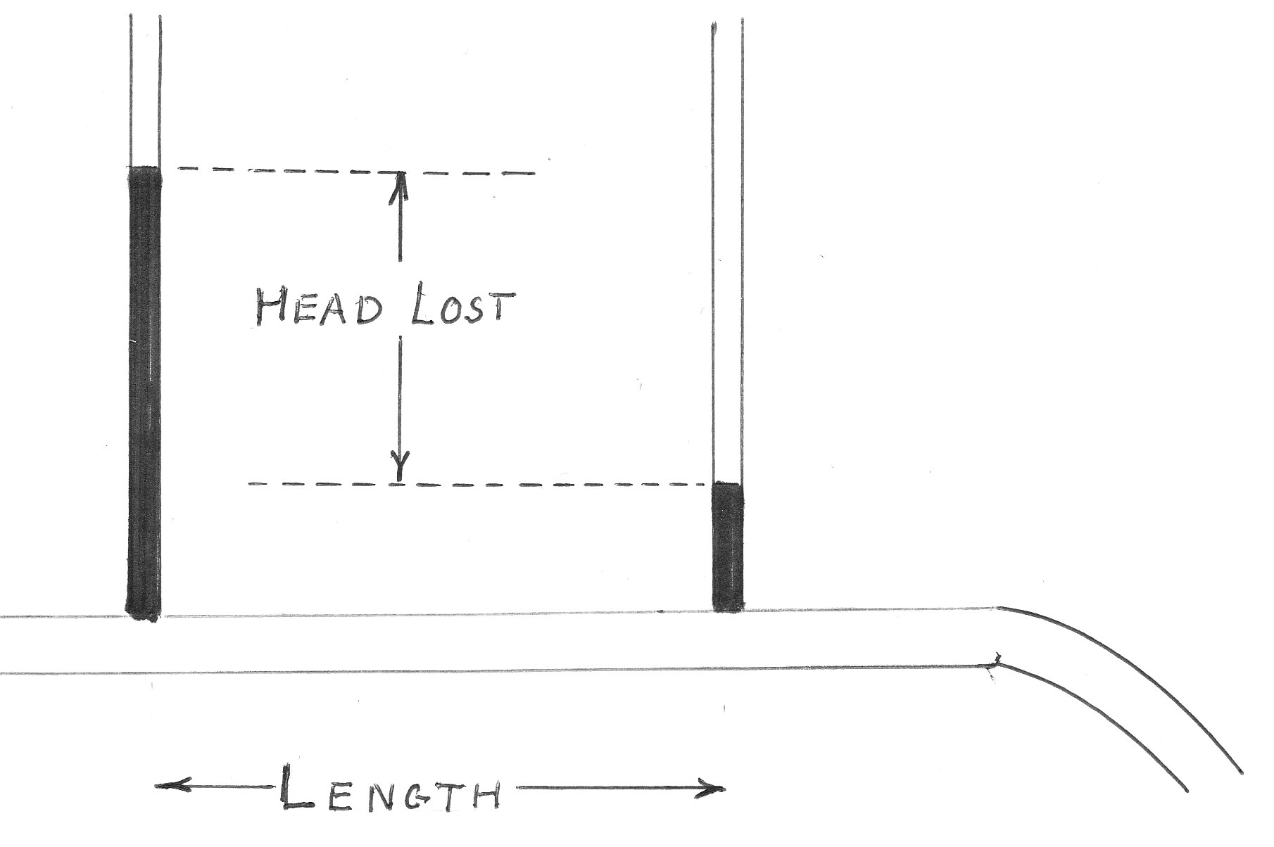
Head Lost due to Friction in the Pipe
Two equations can be used when the flow is either Laminar or Turbulent. These are:-
Darcy's Equation.
This equation can be expressed in terms of the quantity flowing per second.
Using the Imperial system of measurements
Or for non circular pipes
The Chezy Equation
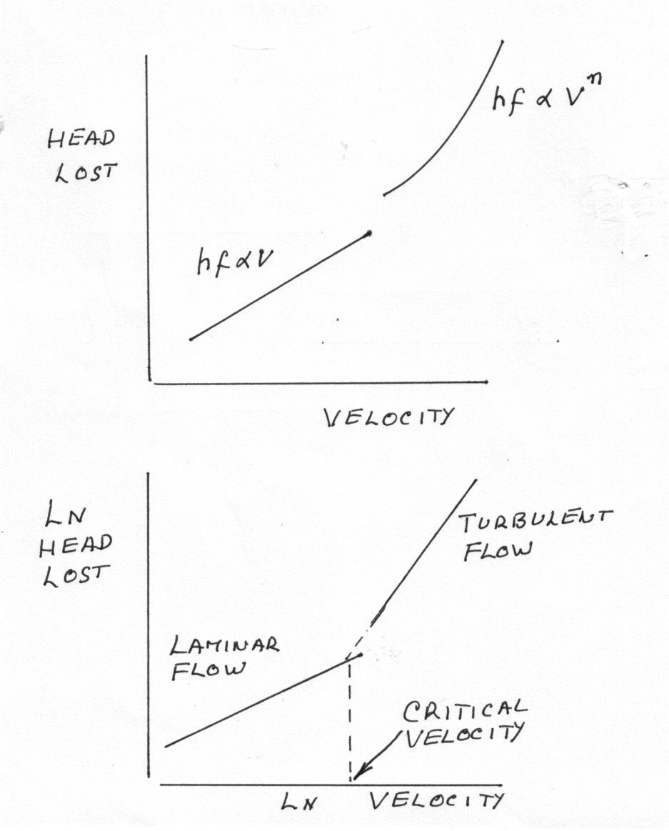
Reynolds number
Which equals 2,300 at the point where the flow changes from Laminar to Turbulent. This is known as the Critical Velocity
Click on the red button to see the proofs of the Darcy and Chezy Equations
Laminar Flow
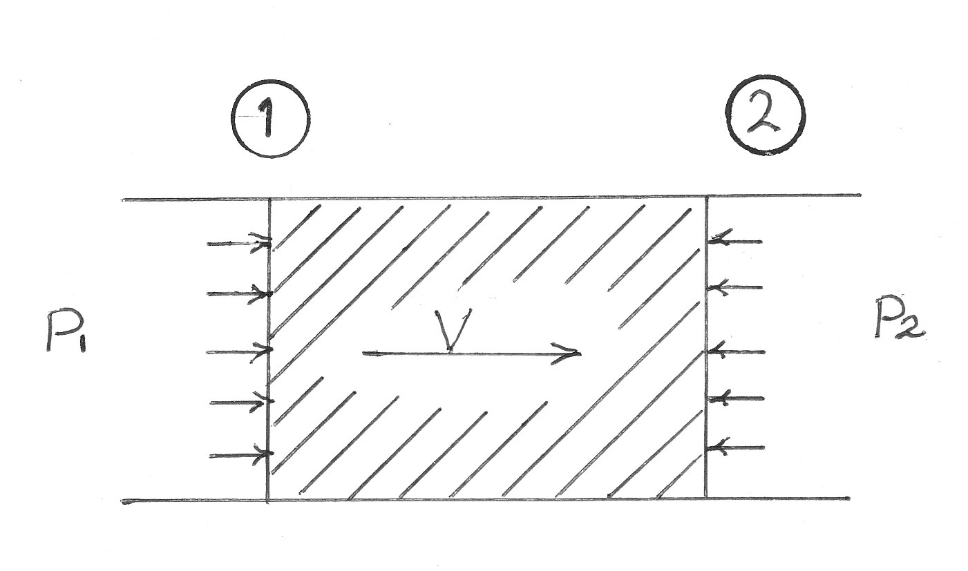
When the flow is laminar it is possible to use the following equation to find the head lost.
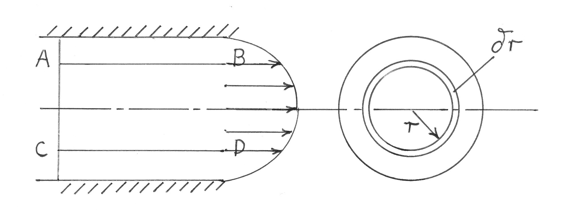
The Poiseuille equation states that for a round pipe the head lost due to friction is given by:-
The proof of this equation is as follows and can be seen by clicking on the red button
Sudden changes to Pipe size or Shape.
The sudden changes or the introduction of bends or valves disturbs the flow pattern along the pipe. The result is an increase in turbulence and this increases the frictional losses.
Sudden enlargement
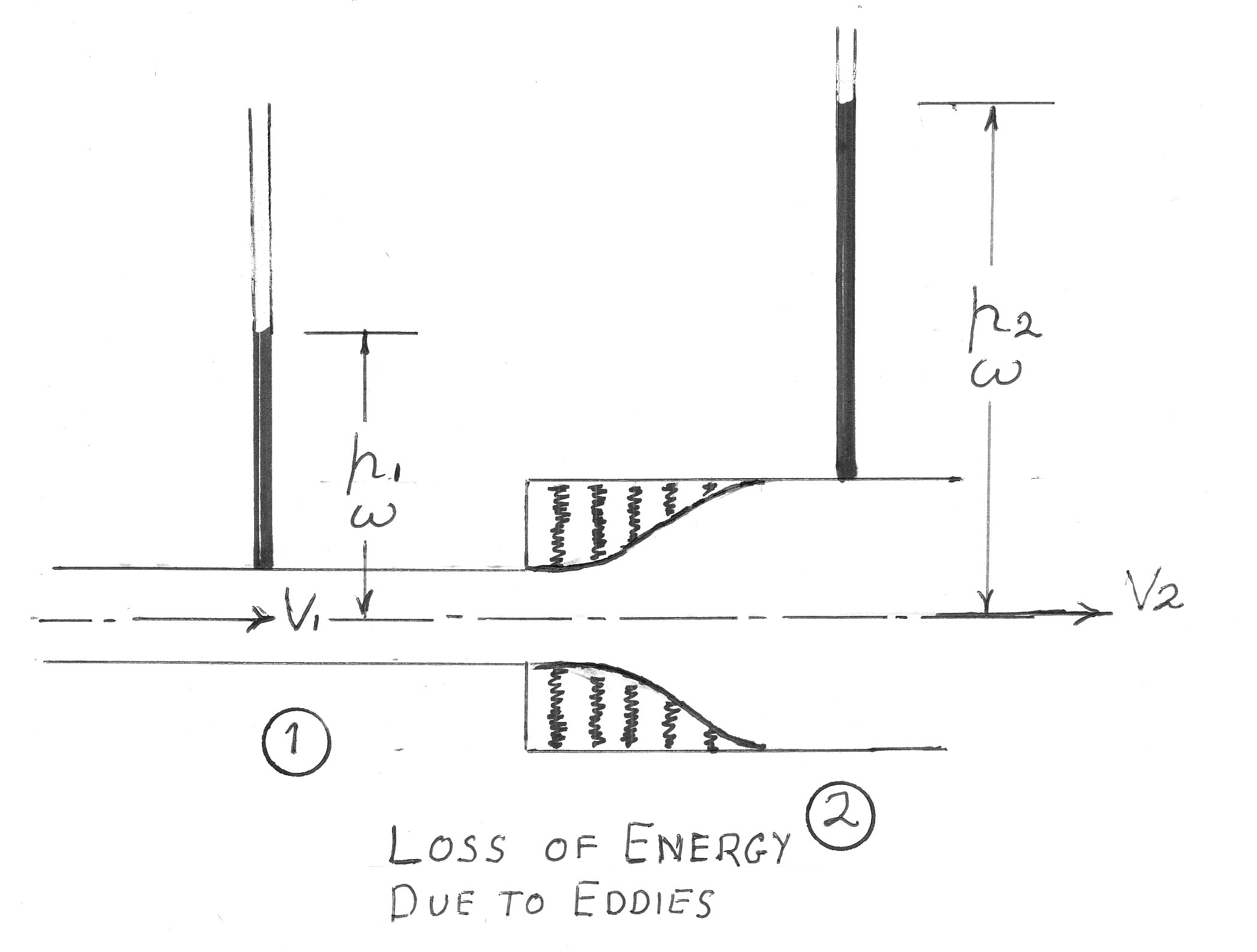
To see the proof of the above equation please click on the red button
Sudden Contraction
As can be seen from the following diagram, eddy currents reduce the effective diameter of the smaller pipe. This causes the loss of head.
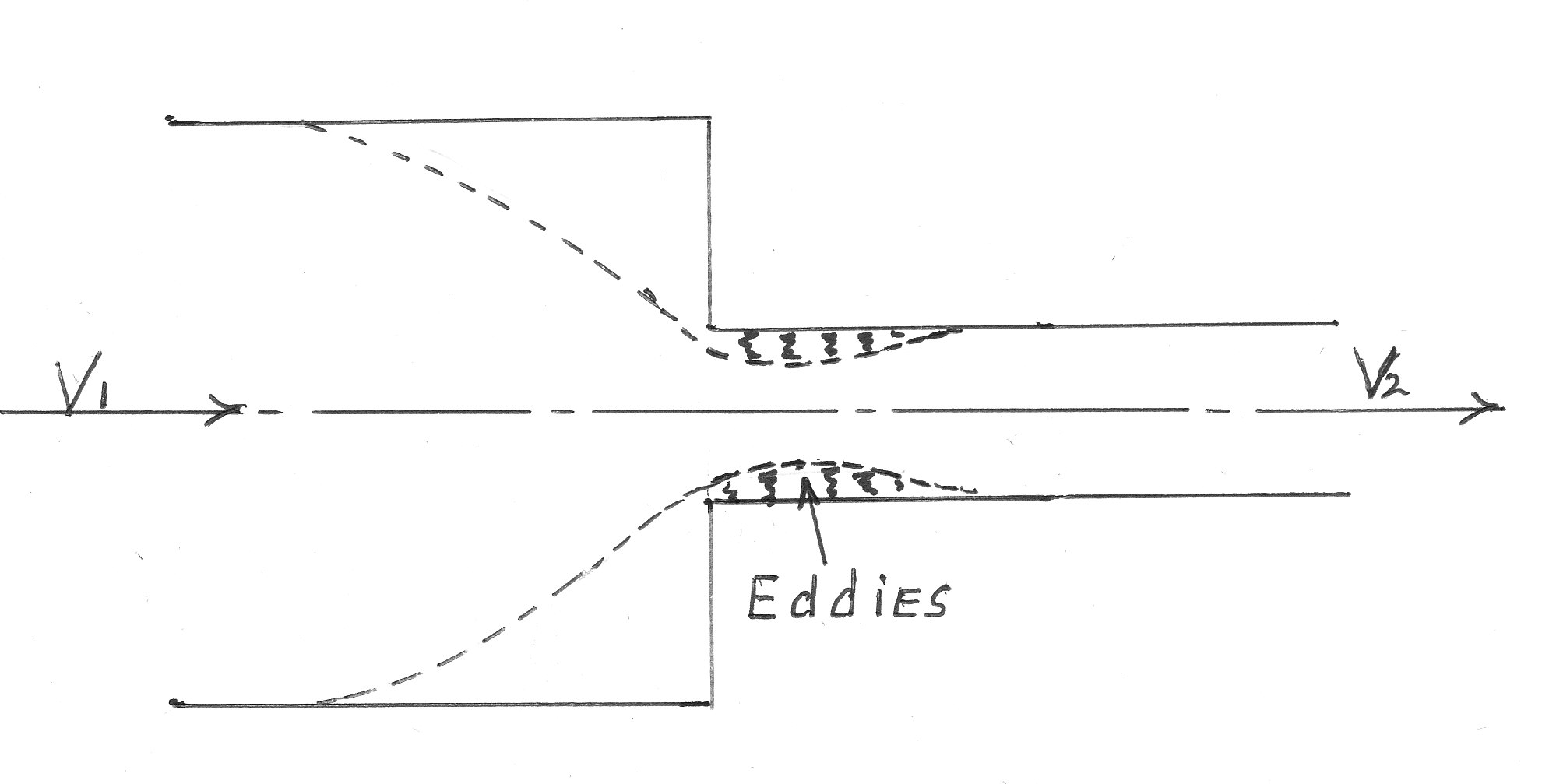
The coefficient of Contraction is defined as :-
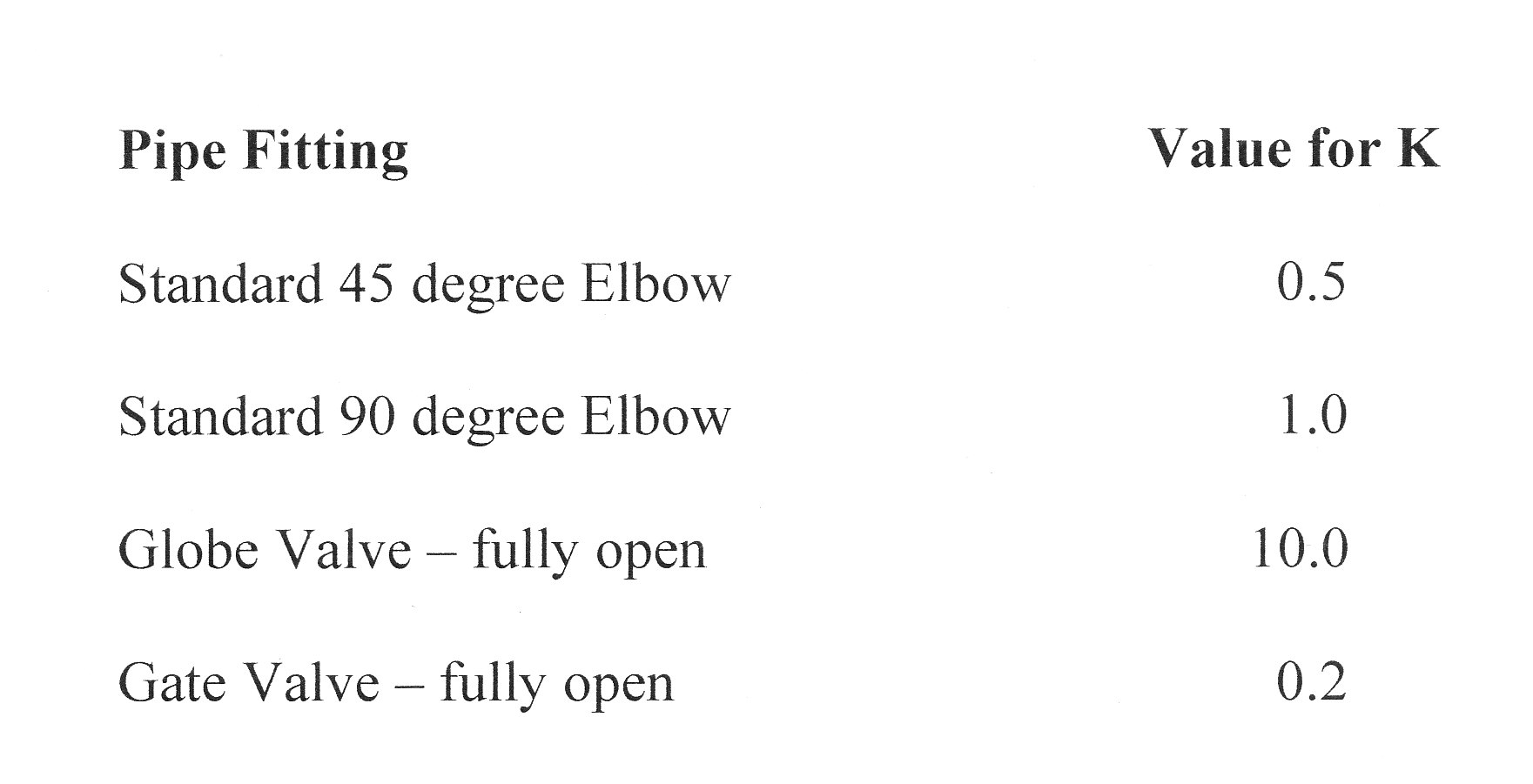
"k" is a constant and in this case is approximately 0.5. The value of k varies with the application and a selection are shown in the table at the end of this section.
To see the proof of the above equation, please click on the red button
Head Lost at an Obstruction (e.g. a Valve)
fig of valve
Bends; Elbows; Gate Valves.
The formula from above hold good but with differing values for K. The following table give some typical values:-
Worked Examples
The workings of all the examples have been "Hidden" and can be seen by clicking on the red button.
Example 1
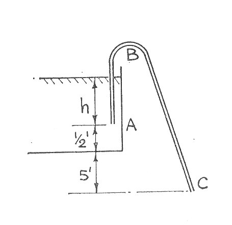
Water is siphoned out of a tank by means of a bent pipe ABC, 80 ft. long and 1 in. in diameter. A is below the water surface and 6 in . above the base sof the tank. AB is vertical and 30 ft long; BS is 50 ft. long with the discharge end C 5ft. below the base of the tank.
If the barometer is 34 ft. of water and the siphon action at B ceases when the absolute pressure is 6 ft. of water, find the depth of water in the tank when the siphon action ceases. F=0.008 and the loss of head at entry to the pipe is:-
Where v is the velocity of water in the pipe (B.Sc. Part 1)
Example 2
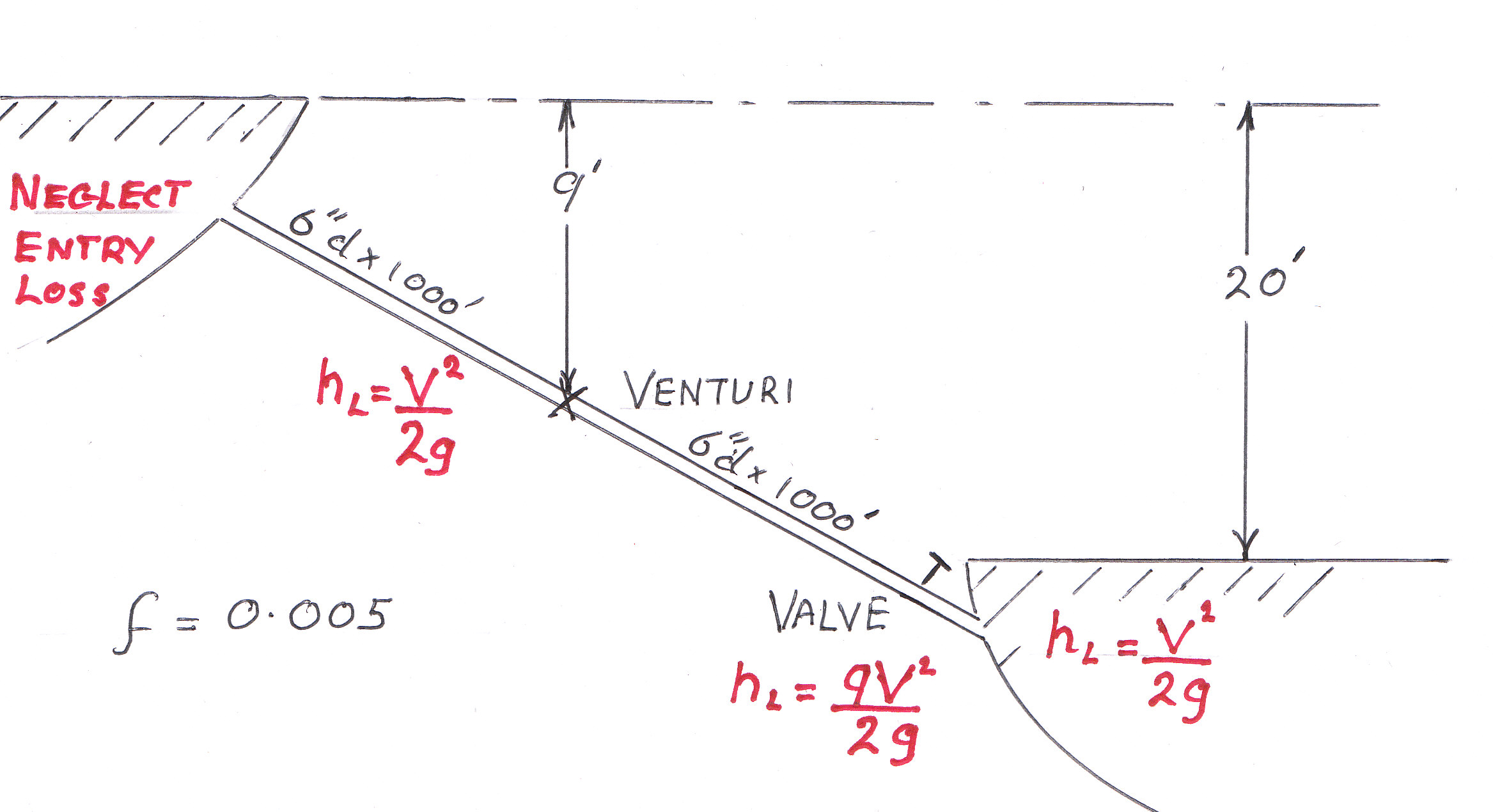
A pipe 6 in. in diameter and 200 ft. long connects two reservoirs who's constant difference in water level is 20 ft. A horizontal venturi meter having an inlet diameter of 6 in. is halfway along thee pipe and is 9 ft. below the level of the upper reservoir. The discharge coefficient for the venturi is unity and the loss of head in its divergent portion is where v is the velocity of flow through the pipe. The frictional coefficient for the pipe is 0.005.
Flow is controlled by a valve at the outlet end of the pipe and when full open, the loss across the valve is . If under these conditions, the pressure head at the venturi throat must not be less than 8 ft. below atmospheric pressure find:-
(a) The minimum allowable throat diameter.
(b) The maximum rate of flow in cusec. ()
Neglect loss of head at the pipe entry. (B.Sc. 1951 Part 2)
Example 3
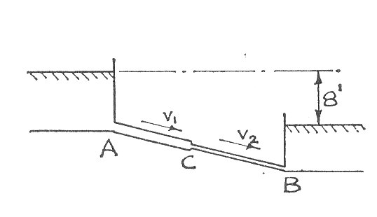
Two tanks A and B are connected by a pipe 100 ft. long. The first 70 ft. has a diameter of 3 in. and then it is suddenly reduced to 2 in. for the next 30 ft. The distance of levels between the tanks is constant at 8 ft. "f" for both pipes is 0.005 and the contraction coefficient at the sudden change in area is 0.58
Find all the losses of head, including that at the sharp edged pipe entry from A in terms of the velocity and at the exit of the 2 in. pipe and hence find the flow in gallons per min.
Example 4
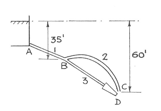
A 6 in.pipe leads from a reservoir to a point 1600 ft. along where it branches into a 3 in.diameter pipe 100 ft. long with an open end and a 4 in. diameter pipe 400 ft. long with a 2 in. diameter nozzle at the end. Both branch pipes discharge into atmosphere at points 60 ft. below the reservoir level.
Calculate the flow in each branch pipe and the pressure at the junction if it is 35 ft. below the reservoir level. Take for the nozzle as 0.96; f for all pipes as 0.01 and assume that all pipe losses, other than pipe friction can be ignored. (B.Sc. Part 2)
To see the workings please click on the red button
Please note that further worked examples on this topic will be found in the paper on "Hydraulic Gradients"
````````