The Hydraulic Gradient
Describes how the friction and other losses effect the Hydraulic Gradient in a pipe subjected to a constant head
You're viewing an older version of this page (#3569). View the current version.
Introduction
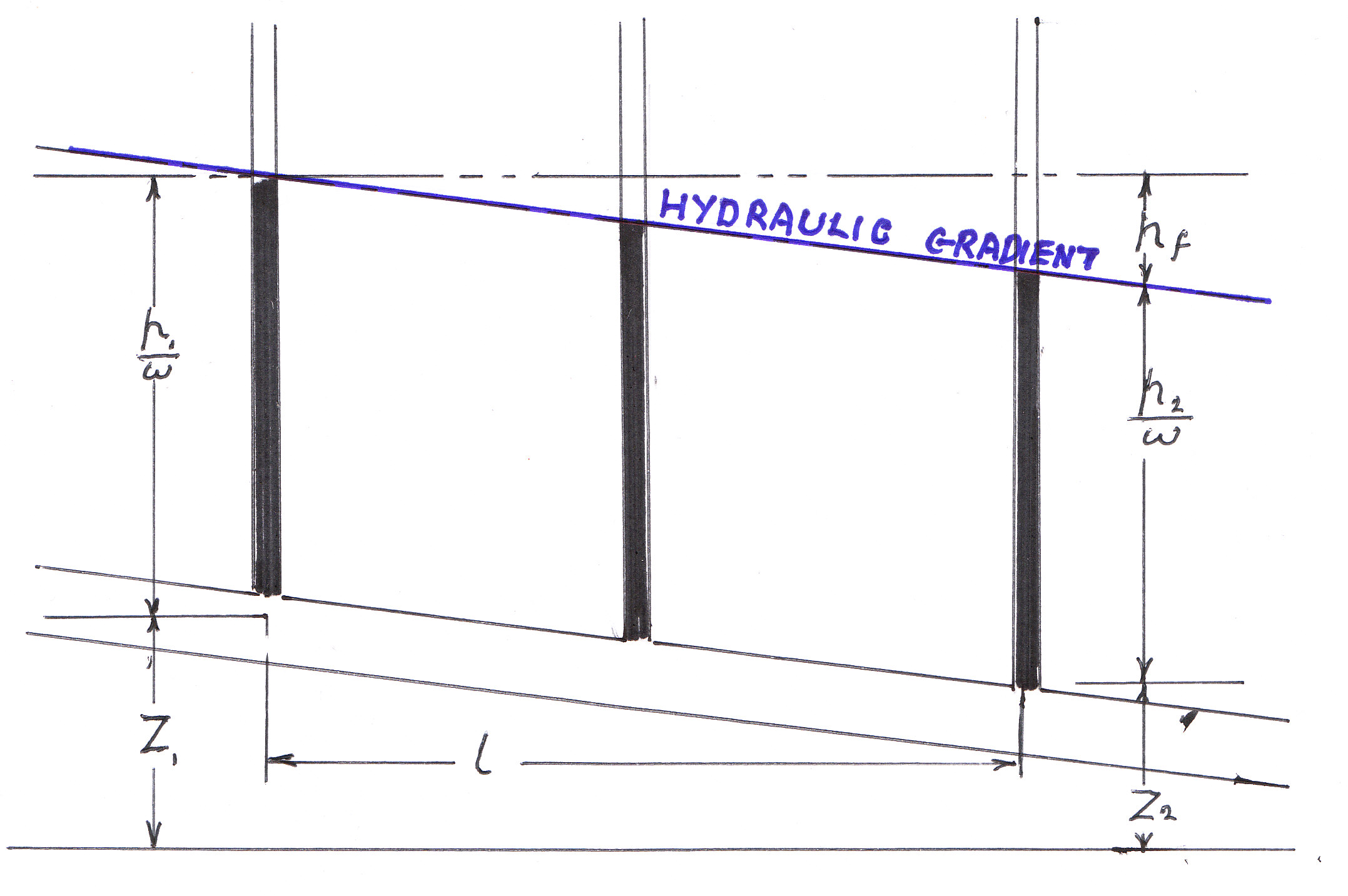
In the pages on the flow of a fluid through pipes, it is seen that there is a loss of head. Whilst some of this is due to the effect of sudden contraction or expansions in the pipe diameter, pipe fittings such as bends and valves and entry and exit losses,a loss of potential head (i.e. The input of the pipe is higher than the outflow) a significant portion is due to the friction in the pipe (The Darcy Equation). However in a pipe of uniform cross section, there will be no loss of velocity head and so the loss of Total Energy will be the result of a loss in Pressure Head. The following diagram shows a uniform pipe and the value of pressure head at three points down its length. The line joining these points is calledThe Hydraulic Gradient
The significance of the Hydraulic Gradient
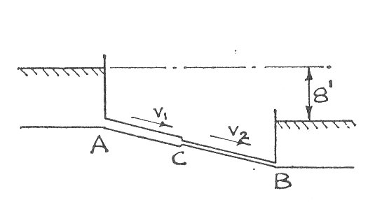
Normally when a pipe is laid, attempts are made to keep the pipe at or below the hydraulic Gradient However in some cases this may not be possible but provided that the pipe does not rise by more than about 26 ft. (8 mtr.) water will still flow. Above this height air comes out of solution and an airlock is formed.
The Hydraulic Gradient
The above diagram is of an extremely simple system. On the next diagram the pipe has both a sudden contraction and an enlargement. The various losses in energy are shown and this is used to construct the Total Energy Line which is shown in red on the diagram.
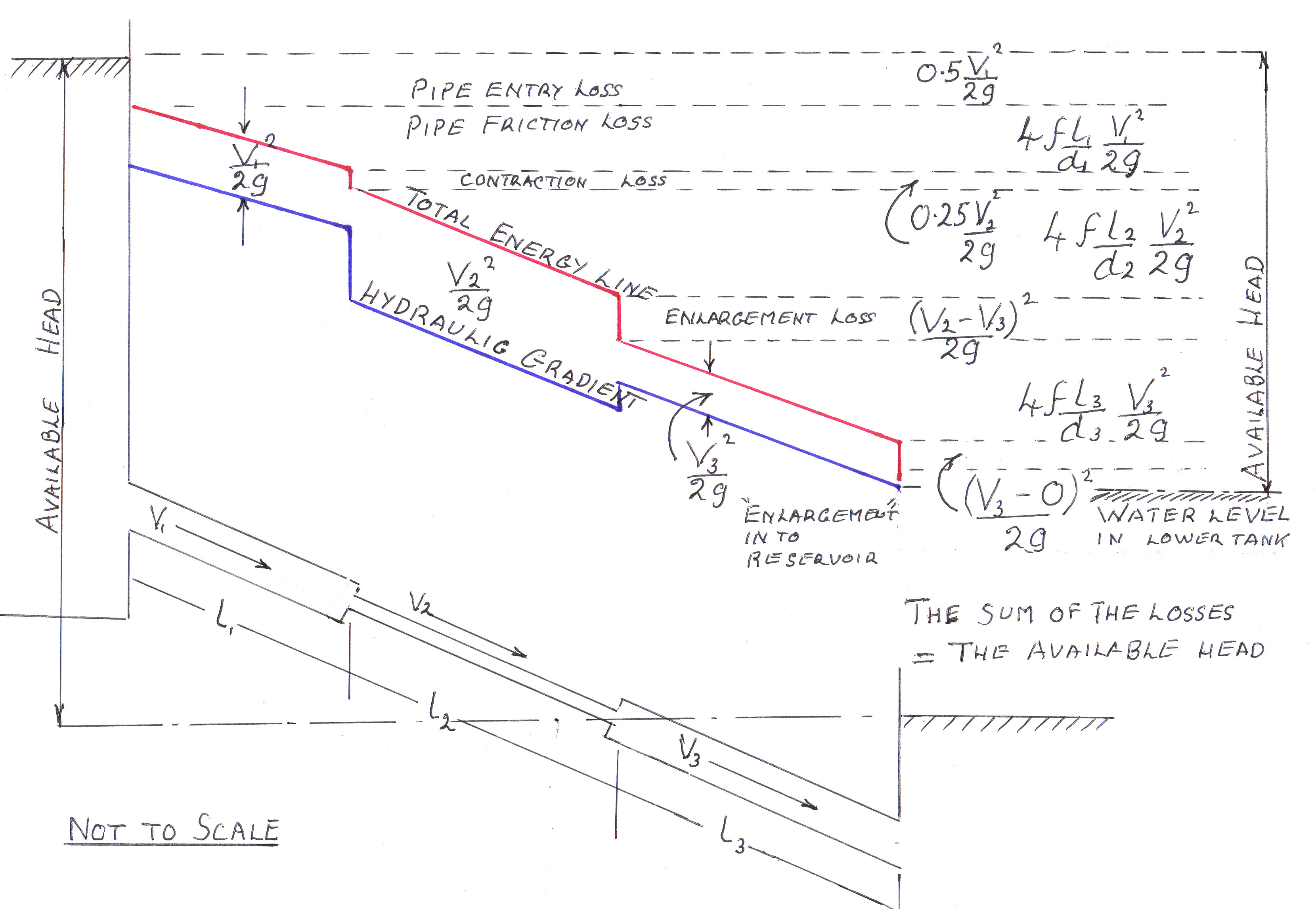
The velocity head at the salient points in the pipe are also calculated and these are subtracted from the Energy Line to give the Hydraulic Gradient which is shown in blue.
Worked Examples
To see the workings please click on the red buttons.
Example 1
Two tanks A and B are connected by a pipe 100 ft. long. The first 70 ft. has a diameter of 3 in. and then the pipe is suddenly reduced to 2 in. for the remaining 30 ft. The difference of levels between the tanks is constant at 30 ft. f = 0.005 and the coefficient of contraction at all sudden changes of area is 0.58
Find all the head losses including that at the sharp edged pipe entry at A in terms of the velocity and hence find the flow in gallons/min. Draw in Hydraulic Gradient diagram.

Example 2
Two tanks, A and B are 100 ft. apart and are connected by two pipes of 2 in. and 4 in. diameter. The height of water in tank A is maintained at 25 ft. above that in tank B. f = 0.008 for both pipes. The coefficient of contraction at pipe entry is 0.585
Calculate the rate of flow in each pipe and draw the Hydraulic Gradient. If the pipes are to be replaced by one larger pipe, calculate the diameter of the pipe required for the total rate of flow from A to B, to remain unchanged.
Drawing of twin pipes from notes
Example 3
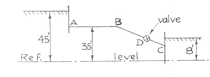
An 8 in. diameter pipeline which connects two reservoirs whose difference of level is 37 ft., consists of a 1000 ft. length AB and a straight 1500 ft. length Bc having a valve 500 ft. from the lower end C, as shown. The pipes AB and BC have each constant coefficients but BC is slightly rougher than AB. When the flow is 600 gal./min. a gauge at B shows that the pressure head of water is 1.7 ft. and the loss of head across the valve is 15 ft.
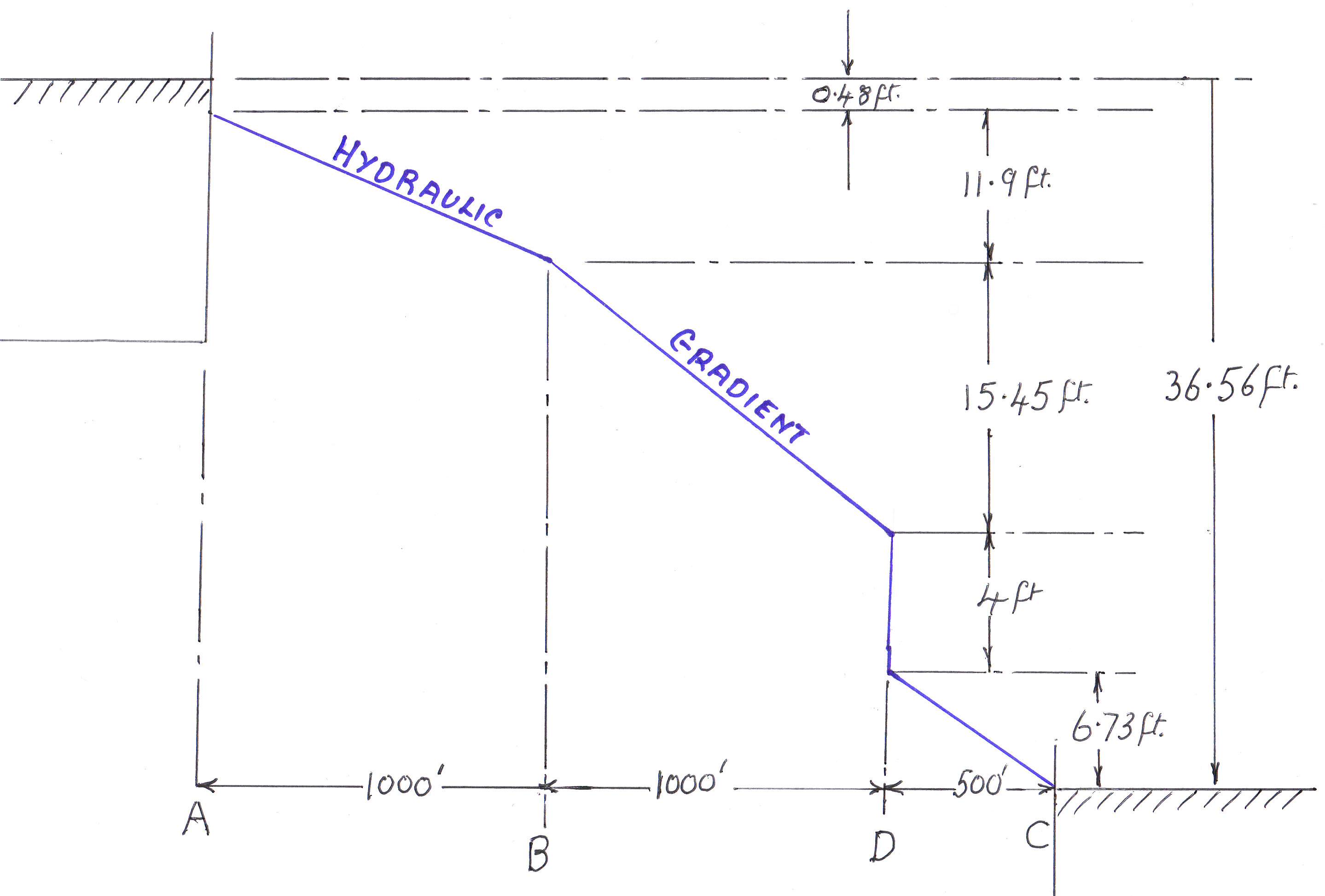
Determine the maximum rate of flow if the loss of head across the valve when fully open is 4 ft. Also draw the Hydraulic Gradient for this quantity.
Allow for the effects of velocity head in the pipe at exit but neglect the loss of head at pipe entry. Assume that the horizontal projection of BC equals its length. (B.Sc. Part1)