
Impulse and Reaction Turbines
A turbine is a rotary engine that extracts energy from a fluid flow and converts it into useful work.
A nozzle is a device designed to control the direction or characteristics of a fluid flow as it exits an enclosed chamber or pipe via an orifice.
Velocity is the measurement of the rate and direction of change in the position of an object. It is a vector physical quantity (both magnitude and direction are required to define it).
Velocity triangles for both Impulse and Reaction Turbines and the Force on the Blades
You're viewing an older version of this page (#3829). View the current version.
Introduction
The vast majority of Turbines consist of a number of curved blades or cups which are attached to a wheel and move. This is actually not always true.
In Southern Sweden, there is a rudimentary wooden turbine which consisted of a wheel with a vertical axis and which was fitted with a number of flat wooden vanes set radially around the circumference. Water entered through three or four wooden "nozzles" of square cross section and after hitting the vanes fell down out of the machine. The efficiency of this arrangement is not known but it is unlikely to be high! It should be added that the head available to the mill was not high.
In Britain water power traditionally relied on Waterwheels.Two sorts were common. The undershot and the overshot. The efficiency of both were poor compared to a modern turbine.
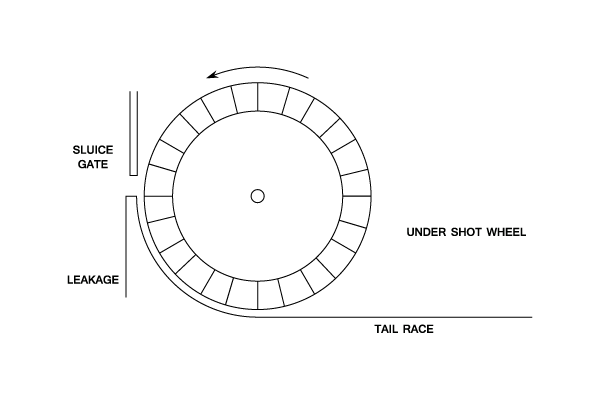
This design worked on a modest head but suffered from the leakage from the wheel. The efficiency was further reduced by the need for the wheel to "push" water along the tail race. It would have been possible to site the wheel clear of the tail race but this would have exacerbate the leakage problem.
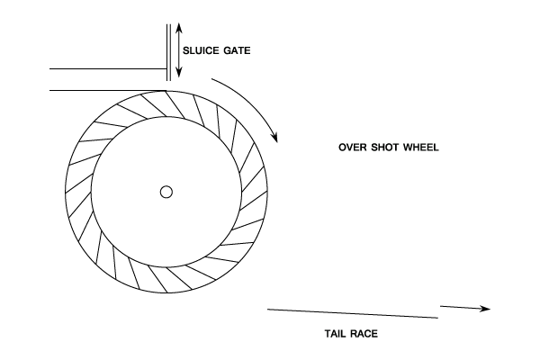
This was more efficient. Clearly as the wheel rotated water spilled from the cups and as a result the wheel did not make full use of the available head
It should be stated that the heads available in Britain, particularly in the Southern part, are in general not more than a few feet and quite unsuitable for many designs of modern turbine.
Velocity Triangles
To analyse the flow through moving curved vanes it is necessary to draw Velocity triangles.
The following symbols are used in their construction.
The Relative Velocity and is tangential to the blades.
Blade Velocity and is Added to
.
The Absolute Velocity and is the vector sum of
and
(Note: The arrows of and
must follow each other around the triangle)
The velocity of whirl (Component of
in the direction of
The velocity of flow (Component of
- The suffix 1 refers to he outlet triangle.
and
are the inlet and outlet angles of absolute velocity.
and
are the inlet and outlet angles relative to the blade velocity.
Axial Flow Turbines
- At Low Speed the velocity triangles are as follows.

- At High Speed, the outlet triangle remains the same but the inlet triangle is now.

Note: and
if there is no friction
Pelton Wheel ( Circumferential )

The two velocity triangles are for low and high flow. The inlet triangle is a straight line.
For both types of flow ( and
).
Jet velocity
Where is the head behind the nozzle and
is the Velocity coefficient.
Weight of water per second,
The blade speed,
Force on the vanes = Mass of water/second multiplied to Change in velocity
Work done on the vanes = Force multiplied to Velocity
The Kinetic energy supplied
The efficiency, Work done / K.E.supplied
For a Pelton Wheel Only
(If friction is ignored.)
But:
For the maximum at a given head and blade angle:
Which occurs when i.e. The bucket speed is half the jet speed. This is a theoretical figure and in practice, due to frictional losses, the maximum efficiency is when
Example 1 [imperial]
The diagram shows a section of a Pelton wheel which has a 2 in. Diam. Jet which produces 2 cubic ft. of water per second. The blade speed is 40 ft/sec and due to friction . ( 1 cubic foot of water weighs 62.4 lbs. and
= 32.2 ft/s.).
Find the Kinetic Energy supplied by the jet per second and the efficiency of the turbine.
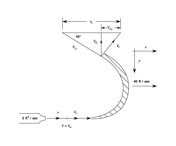
To find the force in the direction:
Jet :
And:
And:
From the outlet triangle:
And:
Also:
In the direction the Force on the vanes = mass of water
change of velocity.
Force on vanes in the direction
The resultant force
The resultant is at i.e. at
to the direction of motion.
Work done per second on the vanes = The force in the direction times blade velocity:
The Kinetic energy supplied by the jet per second
Thus, the efficiency of the turbine
Example 2 [imperial]
Obtain an expression for the work done per lb. of flow by a Pelton Wheel in terms of the mean bucket velocity , the Jet velocity
and the outlet bucket angle
, neglecting all friction losses,
If the loss due to bucket friction and shock can be expressed by:
And that due to bearing friction by :
Where and
are constants , show that the maximum efficiency occurs when
A Pelton wheel runner having a bucket angle of gave on test a maximum efficiency of 0.8 If
is 0.47.
Find and
and hence express the losses as a percentage of the jet energy.
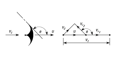
From the velocity diagram is can be seen that:
The change in relative velocity But with no losses
The change in velocity
And the work done per lb.
However there are losses so that:
Useful work done per lb.
The Jet Kinetic Energy per lb. The efficiency,
Where:
Differentiating and equating to zero gives a maximum value for the efficiency when:
i.e. when
Substituting values into the above equation:
From equations (#1) and (#2)
And:
Using Equation (#1)
The Shock Loss And
The Windage Loss
Note: The reminder of the total loss is the loss due to the water leaving the turbine with Kinetic Energy.
- The Shock Loss is
- The Windage Loss is
- The Total Loss is
Turbine with Curved Vanes and an Inward Radial Flow ( Francis or Gerard Turbine)
The following diagram shows the velocity triangles for both low and high speed

Let:
- The weight of water/second striking the vanes be
lb/sec.
- Tangential momentum/second at entry
.
- Moment of momentum at entry =
.
- Moment of momentum at outlet =
.
Then the Torque on the vanes equals the change of moment of momentum per second
The work done per second on the vanes equals the Torque times the angular velocity
But: and
work done/second
This is the Euler equation which can be applied to any type of turbine or centrifugal pumps.
Example 1 [imperial]
Derive an expression for the hydraulic efficiency of a turbine in terms of the tangential velocities of the runner, the velocities of whirl at inlet and outlet and the supply head. Take all velocities in the direction of the runner as positive.
An inward flow reaction turbine discharges radially and the velocity of flow is constant and equal to the velocity of discharge from the suction tube.
Show that the hydraulic can be expressed by:
Where and
are the guide vane angles at inlet.
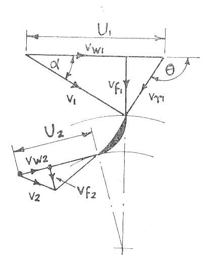
Please refer to the velocity triangles in the diagram.
The Force = The rate of change of Momentum
The available tangential force at the wheel entry And the available useful power at the wheel entry
Similarly the useful power expelled at exit
But the power available
The power given to the wheel
Since is radial
The work done per lb. of water
From the vector triangles it can be seen that:
i.e.
Also:
From the above equations:
The work done per lb.
If there are no guide vane losses:
(where Work done per lb.)
From Equations (#1) and (#2)
Example 2 [imperial]
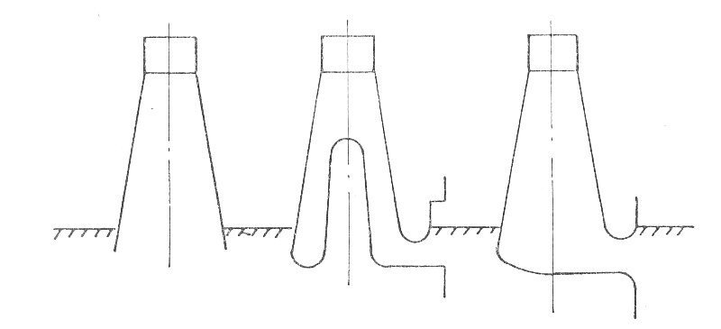
State briefly the reasons for fitting a draft tube to a reaction turbine and sketch three common types.
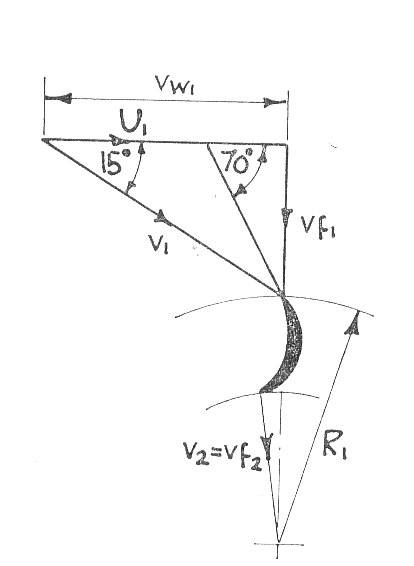
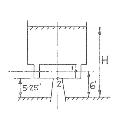
In a vertical Francis Turbine, the runner speed is 380 r.p.m. and the available head across the turbine is 150 ft. The inlet runner is 6 ft.above the tail race level and the area and diameter of the runner at inlet are 2.6 sq.ft. and 3 ft respectively. The guide and runner vane angles at inlet are shown in the diagram.
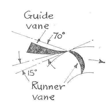
The water enters a draft tube without whirl 5.25 ft. above the tail-race and the draft tube diameter here is 1 ft. 10 in. At outlet the draft tube diameter is 2 ft. 4 in. If the frictional losses in the runner amount to 9 ft.lb/lb and in the draft tube 5 ft.lb./lb. and the overall efficiency is 0.9 X the hydraulic efficiency.
Find:
- The B.H.\b{P}. of the Turbine.
- The hydraulic efficiency.
- The pressure head at the inlet to the runner in ft.lb./lb.
- The pressure head at the entry to the draft tube in ft.lb./lb.
The reasons for fitting a draft tube are that it allows the turbine to be mounted above the tail race without there being a significant loss of head a loss of head. In addition because of the gradual increase in cross section the discharge velocity from the turbine is not all wasted as some is converted into useful a pressure head.
Three types of draft tubes are shown in the following sketch. From the left these are a simple cone, spreading and elbow types.
For the calculations please refer to the following two diagrams:
i.e.
The work done per lb.
Thus the Hydraulic Efficiency
The overall Efficiency,
Therefore the B.H.P.generated is given by:
- For the Draft tube
= A Constant and therefore if
is the exit velocity from the draft tube:
And:
The total head, Guide loss + Rotor loss +Work done + Draft-tube loss +
i.e.
Therefore, Guide loss
If suffix 1 refers to the runner inlet and suffix 2 refers to the draft-tube inlet then:
Also:
- Work done/lb. - Rotor loss
i.e.
i.e.
below atmospheric pressure
Thus:
- The B.H.\b{P}. of the Turbine is
- The hydraulic efficiency is
- The pressure head at the inlet to the runner in ft.lb./lb. is
- The pressure head at the entry to the draft tube in ft.lb./lb. is