
The Efficiency of Turbines
The Efficiency of both Impulse and Reaction Turbines
You're viewing an older version of this page (#3590). View the current version.
Introduction
This section considers the efficiency of both Impulse and Reaction Turbines. As a generality the efficiency of turbines is a function of the available head. The lower the head the lower the efficiency. This will be of great importance in the utilisation of Tidal Power. Whilst there is usually plenty of water the available heads are low. The proposed Seven Barrage in England has the second highest tide in the World but the neap tide range is only 28 ft.
The Efficiency of Turbines
This will be considered under two heading representing the different types of Turbine.
Impulse Turbines ( No allowance for frictional losses)
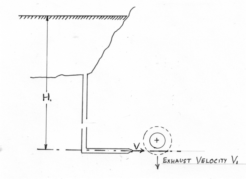
Let
- H be the total head behind the nozzle i.e. the sum of the pressure and velocity heads. This equals
- V = Jet Velocity
= the exhaust velocity of water leaving the vanes.
- Thus
-
- The Work done per second on the vanes ( per lb of water per second)
$=
Impulse Turbine allowing for friction
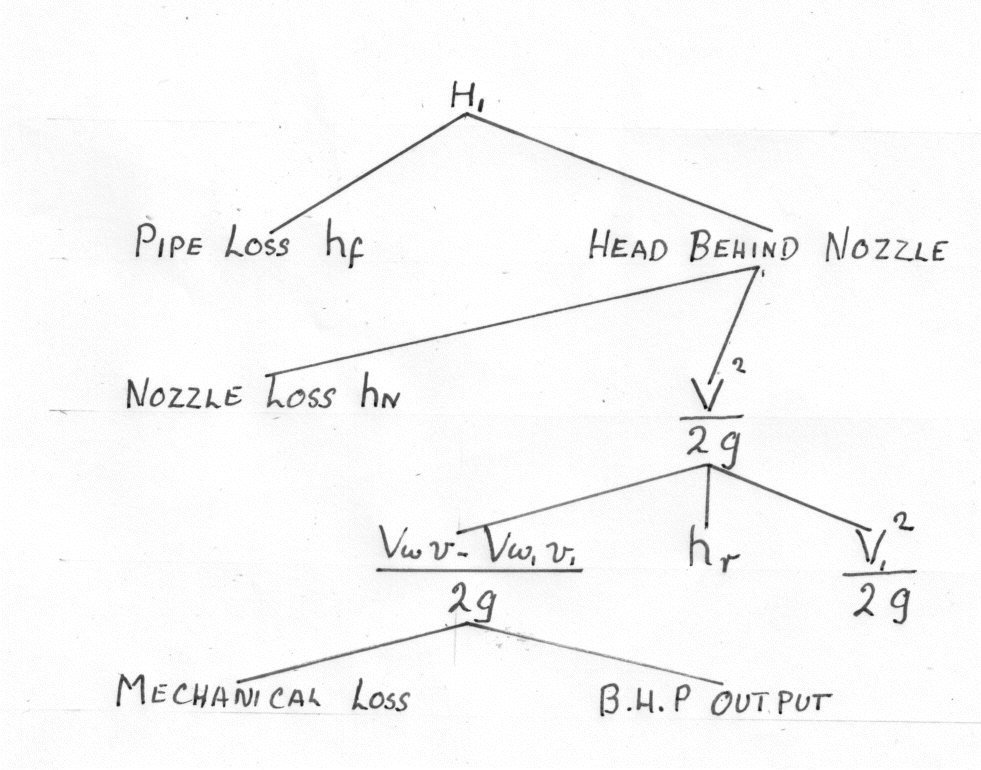
The frictional losses are in the nozzle (), the runner and various mechanical losses(
)
The effect of these is to reduce V i.e. to reduce the hydraulic efficiency
- (2)
- (3)
The Actual Hydraulic Efficiency of the Turbine
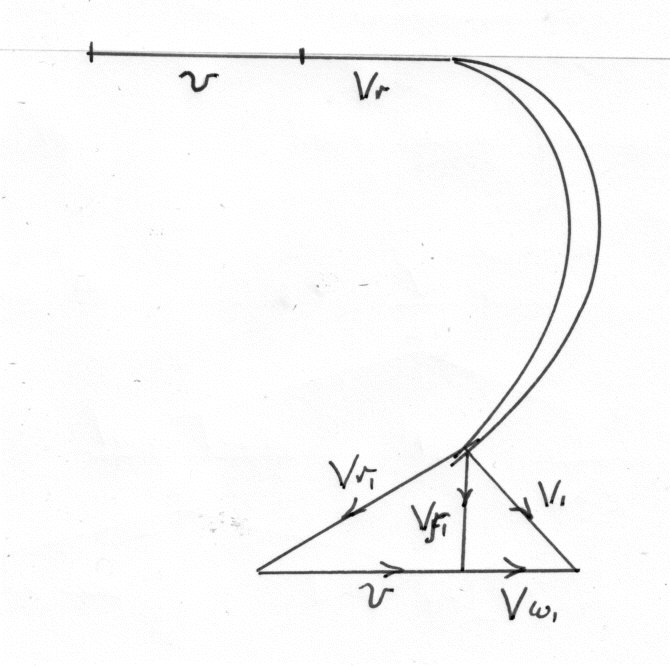
The latter is based upon values obtained from the velocity triangles and momentum considerations and will thus take into account the various changes in velocity due to friction.
The Actual(overall efficiency) is based on the useful work output divided by the water power input. It therefore makes allowance for all frictional losses.
Example 1
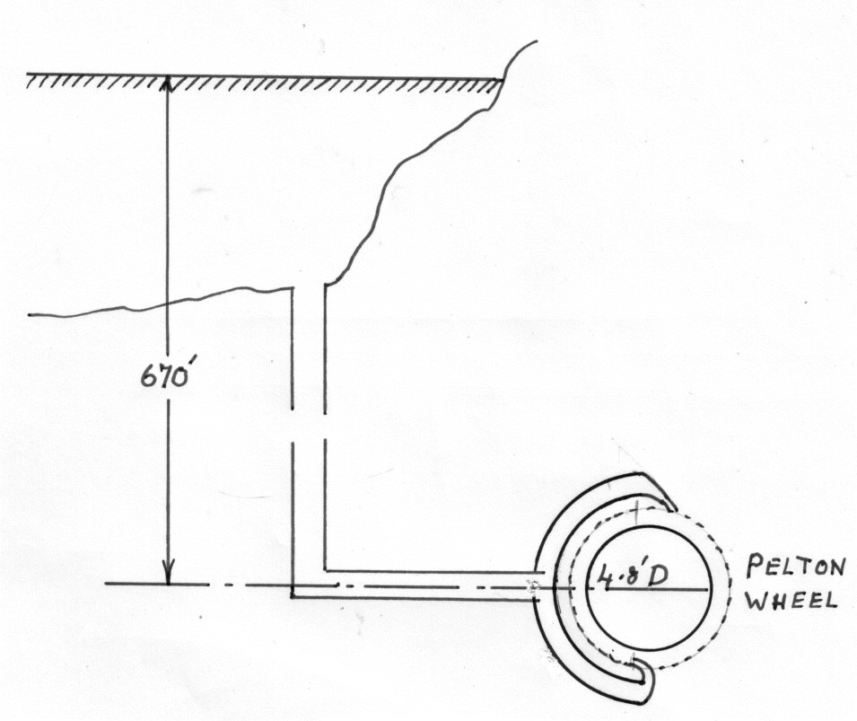
A Pelton wheel is driven by two similar jets, transmits 5000 Horse Power to the shaft running at 375 r.p.m. The head from the reservoir level is 670 ft. and the efficiency of power transmission through the pipeline and nozzles is 90% The centre lines of the jets are tangential to a 4.8 ft. diameter circle. The relative velocity decreases by 10% as the water traverses the bucket surfaces which are so shaped that they would, if stationary deflect the water through an angle of 165 degrees.
( one Horse Power (HP) is 550 ft.lb/sec. One cubic ft. of water weighs 62.4 lb. g = 32.2 ft/second squared)
Neglecting windage losses find:-
- 1.The efficiency of the runner
- 2.The diameter of each jet.
To see the solution to the above question please click on the red button
Reaction Turbines
This section covers Inward Radial flow; Mixed flow; or Axial Turbines with a propeller shaft. These may be sited below the tail race or above it with a draft tube.
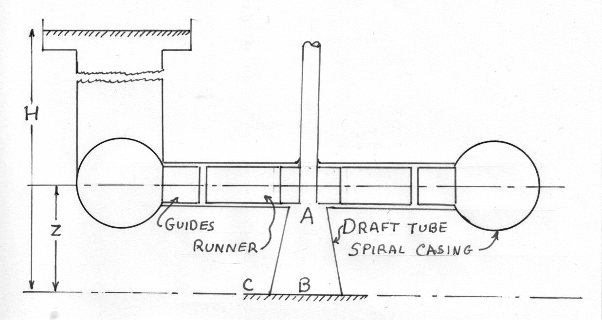
Let
- V be the absolute velocity at the entry to the runner
be the absolute velocity at the exit of the runner
- H be the head.
Where the Supply is low it is usual to have an open flume supply with a short Pinstock e.g. as found in a Propeller Turbine. In this arrangement the head H is the vertical height from the water level in the "fore bay" to the level in the ail Race.
For larger heads the Pinstock is longer and there is a smaller throughput of water e.g A Radial Flow Francis Turbine. H is now the Total Head in the Supply Pipe just before entering the Turbine casing i.e. Pressure Velocity and Datum . Where appropriate measurements are relative to the Tail Stock Datum.
The Gross Head is measured from the the supply reservoir and includes \b{Pinstock Losses
Draft Tube
The Draft Tube is designed to convert Kinetic Energy of the water being discharged into a reduced Pressure. This gives increases the suction through the Turbine and enables the height Z ( see diagram) to be included in the Supply head H.
Apply Bernoulli at A and C (see diagram)
In practice the height Z is limited to avoid cavitation at A ( See. Fluid Mechanics - Cavitation)
If there are no losses in the runner; the supply system or draft tube.
Then the work done by the water on the runner (W.D.)
(if there is no Draft tube or if it is parallel)
The Theoretical Hydraulic Efficiency η
NOTES
1. For a Reaction Turbine
2. For Axial Flow
For radial flow
Velocity of Flow
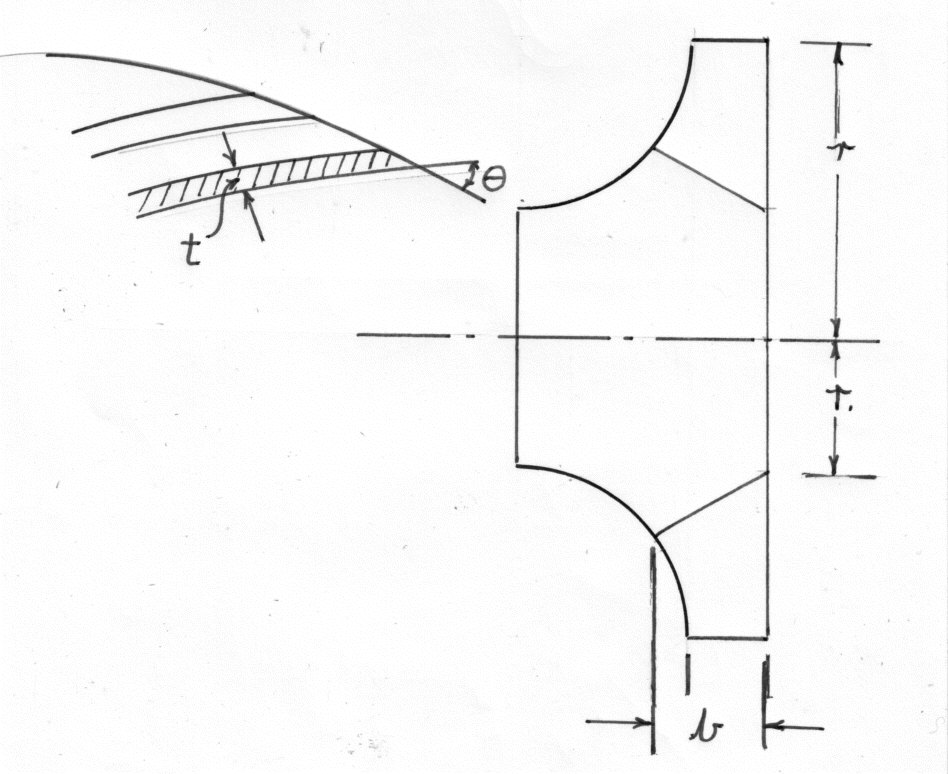
{NB. Reaction Turbines run full}
Let:-
- s be the number of blades;
- T be the blade thickness
- b be the width of the
runner.
Thus the circumferential area of flow at inlet is:-
Where k is the blade factor
Therefore the rate of flow through the Turbine
Similarly at the outlet
Unless otherwise stated it is normal to take
Variations of pressure head across the Turbine passage. Assuming no losses
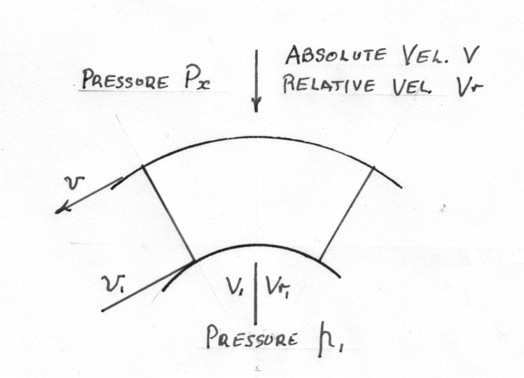
Applying Bernoulli to the absolute flow
Example 2
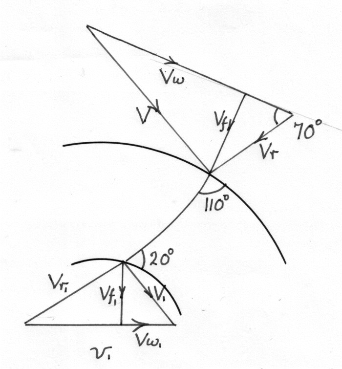
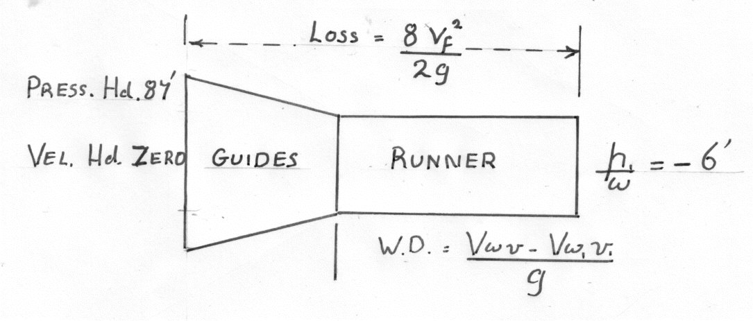
In a Francis type Turbine, the guide-vane angle is 8 degrees, the inlet angle of the moving vanes is 110 degrees and the outlet angle is 20 degrees ( see diagram). Both the fixes and moving vanes reduce the flow by 15%.
The runner is 24 inches outside diameter and 16 inches inside diameter and the widths at the entrance and exit are 2 and 3 inches respectively.
The pressure at entry to the guides is + 87 ft.head and the kinetic energy there can be neglected. The pressure at discharge is - 6 ft.head.
If the losses in the guides and moving vanes are taken as where f is the radial component of flow calculate:-
a)The speed of the runner in r.p.m. for tangential flow on to the running vanes
b) The horse-power given to the runner by the water.
Note. For more examples which include Turbine Efficiency please see the Section on Impulse and Reaction Turbines.