
Field Strength
Key facts
The magnetic field strength is defined as:
For an isolated conductor of radius , the magnetic field strength is:
The magnetic field strength is related to the magnetic flux density by the equation:
where is the magnetic permeability of free space, and
is the relative magnetic permeability of the material.
<br/>
Constants
A description of the magnetic field strength, also considering its relation with the magnetic flux density
You're viewing an older version of this page (#3611). View the current version.
The magnetic fields generated by electric currents are characterized by the magnetic flux density , measured in
. But when the generated fields pass through magnetic materials which themselves contribute internal magnetic fields, ambiguities can arise concerning what part of the field comes from the external currents, and what part comes from the material itself. In order to clarify this issue, we introduce another magnetic field quantity, the magnetic fields strength
, which unambiguously designates the magnetic influence from external currents, independent of the material's magnetic contribution.
The magnetic field strength can be broadly defined by:
where is expressed in amperes/meter, and the current
in amperes.
For the particular case of an isolated conductor of radius , as the one diagramed in Figure 1:
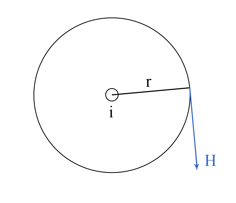
the magnetic field strength can be defined by writing that:
which leads to:
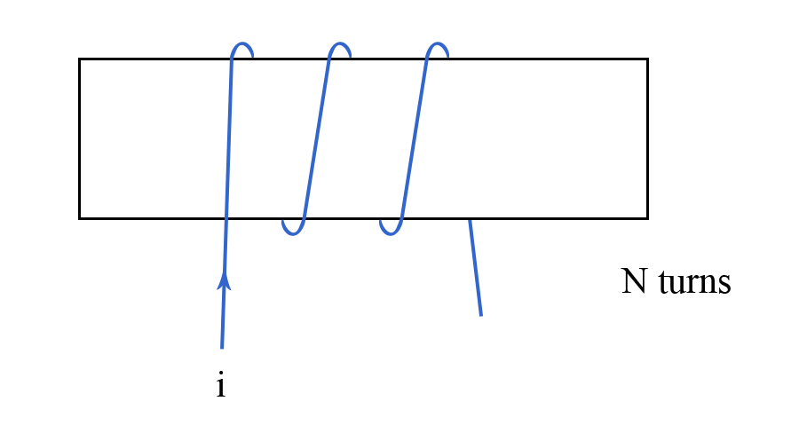
As was previously noted, magnetic materials, such as iron, can contribute internal magnetic fields. Indeed, iron contains within its atoms a number of tiny current loops. Normally, their random distribution produces no effect. However, when a current flows, these current loops become oriented, the magnetic effect due to the iron becomes more important, and the resulting current is much higher than it would have been without the iron. We can thus write that:
where is the current in the coil, and
is the number of turns, while
represents the equivalent effect of the atomic current loops (see Figure 2).
We redefine in iron to retain the magnetic circuit law in terms of the known current
:
Thus, we can write that:
Magnetic Field Strength and Magnetic Flux Density
A commonly used relation between the magnetic flux density and the magnetic field strength
is:
where , the magnetic permeability, is:
In (#8) is the magnetic permeability of free space, also known as the magnetic constant:
and the relative magnetic permeability of the material.
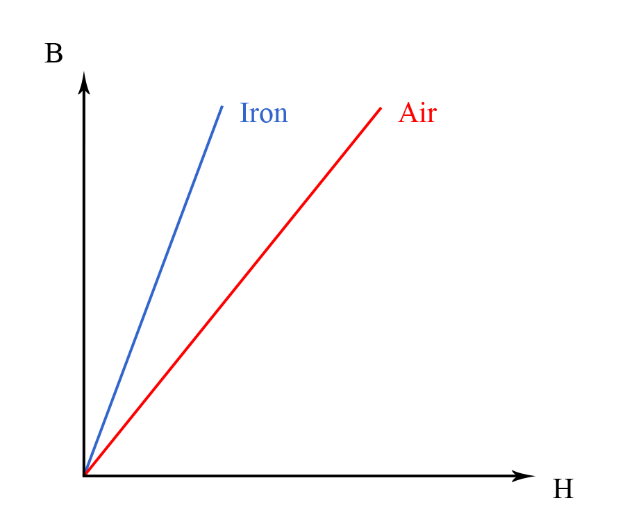
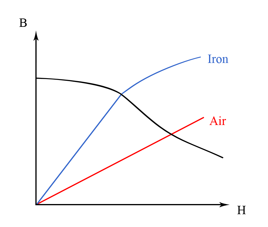
Thus, the magnetic flux density in air can be written as:
whereas the magnetic flux density in iron as:
where is the relative magnetic permeability of iron (for example graphs see Figures 3 and 4).
Reference
Example 1 [metric]
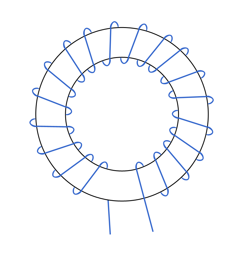
Given a toroid with the mean diameter of and the cross section of
(see Figure E1), calculate the number of ampere-turns (
) which would give a magnetic flux of
.
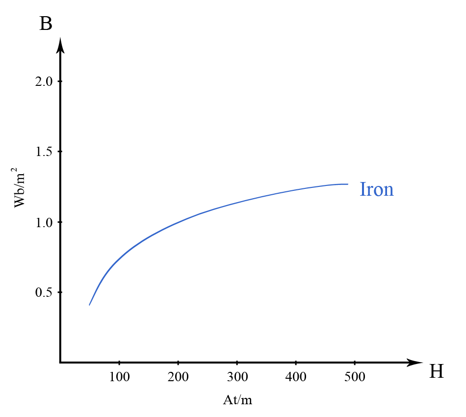
The curve for iron is given in Figure E2:
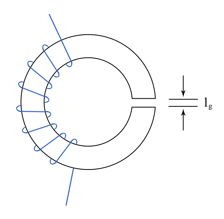
Also, calculate the number of ampere-turns required to give the same magnetic flux in the hypothetical case that the toroid has an air gap of length (see Figure E3).
Given that the cross section of the toroid is (
), the magnetic flux density in the iron should be:
Therefore, from Figure E2, we obtain:
As the mean diameter of the toroid is (
), we thus obtain the required ampere-turns:
In the case that the toroid has an air gap, we can write the number of ampere-turns for the air gap as , or, furthermore, as
. Taking into account that
,
(from equation #1), and
, we get the required ampere-turns for the air gap:
Taking into account (#3) and (#4), we obtain the total required ampere-turns for the toroid with an air gap:
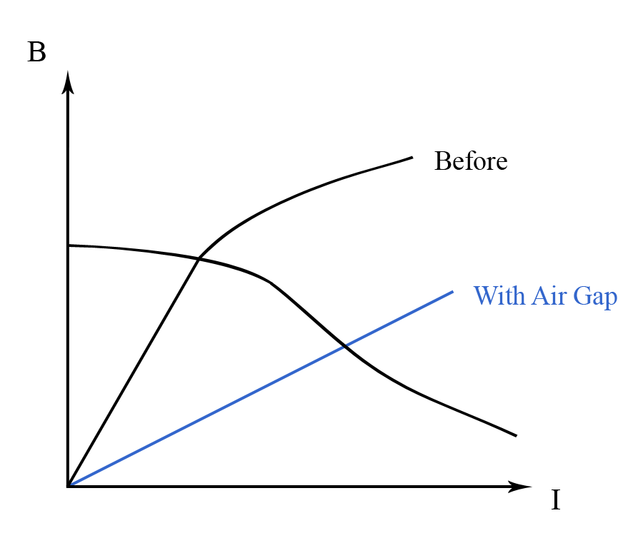
As a side point, it can be noted that the effect of putting an air gap into a toroid is to alter the curve to an almost linear relationship, as diagramed in Figure E4.
For the toroid without an air gap, the required ampere-turns are:
For the toroid with an air gap, the total required ampere-turns are: