
Inductance
Key facts
The inductance of a circuit characterized by the magnetic flux , and through which passes a current of
amperes through a coil of
turns, is:
For a circuit passed by a coil of N turns, and characterized by the length , cross-sectional area
, and relative magnetic permeability
, the inductance can also be calculated as:
where is the magnetic permeability of free space.
For a coupled coil circuit, the emf induced in coil 2 due to changes in coil 1 can be expressed as:
where , the mutual inductance, is given by:
The induced voltage of two coils in series with additive turns is given by:
or, if the turns would have been opposite:
The energy stored in a magnetic field can be expressed in terms of inductance as:
where is the current through the inductor
<br/>
Constants
Inductance of a circuit, mutual inductance, and the energy stored in terms of inductance
You're viewing an older version of this page (#3619). View the current version.
In order to define the inductance, consider a coil of wire as the one diagramed in Figure 1.
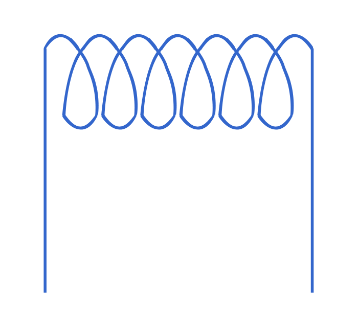
The induced voltage at any instant is:
where is the number of wire turns, and
the magnetic flux. As we can also write that:
equation (#1) becomes:
The term is denoted by
and is called (self-) inductance. Thus, the inductance is:
and equation (#3) becomes:
Inductance can be illustrated by the behavior of a coil of wire which resists any change of electric current that passes through it. The unit of inductance is the Henry (). Thus, a coil has an inductance of
if an induced voltage of
flows through it with a rate of change of current of
.
Calculation of Self Inductance
In order to calculate the self inductance, consider a circuit of length and cross-sectional area
, which is passed by a coil of
turns (see Figure 2).
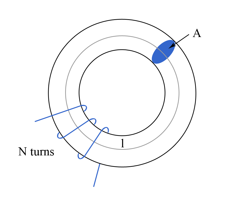
Also, assume that the area of the core is small, and that the magnetic field strength is constant across the area. We can then write that:
or, furthermore, that:
where is the current which passes through the coil (for a more detailed discussion on the magnetic field strength see Field Strength ). We also know that the magnetic field strength
is related to the magnetic flux density
by the equation:
where is the magnetic permeability of free space, and
the relative magnetic permeability. Taking into account (#7), equation (#8) becomes:
As the magnetic flux density is defined as:
where is the magnetic flux, equation (#9) becomes:
from which we obtain the magnetic flux as:
From the definition of the inductance (see equation #4), we can also write that:
\calc{A*((4*π*10^(-7)*mu_r*N^2)/l)} "Instant calculator eq(14)"
Using (#12) in (#13) gives the following expression of the self inductance:
Mutual Inductance
Mutual inductance represents the generation of an electromotive force () in a coil as a result of a change in current in a coupled coil as the one diagramed in Figure 3.
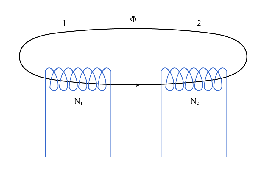
The induced in coil 2 due to changes in coil 1 can be expressed as:
or, furthermore, as:
We defined the mutual inductance between coil 1 and coil 2, , as:
In this definition, represents the ratio between the
generated in coil 2 and the change in current in coil 1 responsible for generating this
.
In the case of no magnetic saturation, the mutual inductance can be written as:
Using (#17), equation (#16) becomes:
The best known application of mutual inductance is the transformer.
The Reciprocal Property of Inductance
Consider the coupled coil circuit diagramed in Figure 4.
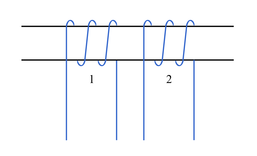
From our previous discussion on mutual inductance, and also considering that there is no magnetic saturation, we can write that:
and also that:
Taking into account (#20) and (#21), we can write that:
As the two coils are wound on the same core, we have that and
. However, for more complicated cases, such relations are harder to see.
The Induced Voltage of Two Coils in Series using Inductance
Consider two coils arranged in series, as diagramed in Figure 5.
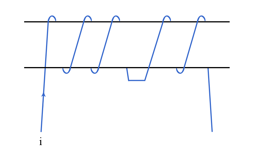
There are four induced electromotive forces due to self and mutual inductance. As such, the induced voltage at any instant can be written as:
or, furthermore, as:
where is the inductance of the first coil,
the inductance of the second coil, and
the mutual inductance.
Equation (#24) applies only when the turns are additive. If the turns are opposite, equation (#24) becomes:
where the term is called equivalent inductance.
Energy Stored in Terms of Inductance
The energy stored in a magnetic field can also be expressed using the (self-) inductance (for a more detailed discussion on the energy stored in a magnetic field see Stored Energy ). For example, equation (#5) can also be written as:
or, furthermore, as:
As the energy released from the coil in a time is:
\calc{(L*I^2)/2} "Instant calculator eq(29)"
and also taking into account (#27), we can write the energy stored in terms of inductance as:
where is the current through the inductor.