
Basic Aerodynamics Theory
Key Facts
Definitions
Law of Conservation of Energy Energy can neither be created, nor destroyed. It can only be said to change its state from one to another. As such, the total energy in any given system is always a constant.
Bernoullis principle
For a perfect incompressible liquid, flowing in a continuous stream, the total energy of a particle remains the same, while the particle moves from one point to another.
Kutta condition
A body with a sharp trailing edge which is moving through a fluid will create about itself a circulation of sufficient strength to hold the rear stagnation point at the trailing edge.
Lift
It is the component of force acting upwards and perpendicular to the line of flight, in a steady, undisturbed stream of air. It is important to note that 'upwards' implies to the roof of the aircraft in all attitudes of flight, i.e. Upright, Banked (as during a turn), and Inverted.
Understanding how an aeroplane derives lift with the Bernoulli's equation, and looking at the forces acting on an aeroplane in flight.
You're viewing an older version of this page (#4110). View the current version.
Introduction
Aero-dynamics is the study of the dynamics associated with the motions of air over a moving object. When an aircraft accelerates down the runway to take off, it produces a relative motion between the air and the aircrafts wings. It is this rush of airflow over and below the wings, created by the aircrafts forward motion, which produces lift and consequently makes all forms of powered flight possible.
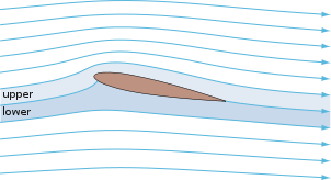
The contours of the upper and lower surfaces of the wing contribute largely to the pressure differences that occur between the two surfaces. The resulting pressure leads to a net force that provides 'Lift' to the wing.
In this section, we use the Bernoulli's and Euler's equations to understand how an aeroplane derives lift. We also look at the four principle forces acting on an aircraft in flight, at ALL times.
Airflow over an aerofoil
Bernoulli's Equation
As with all applications of the Bernoulli's principle, we shall assume that the flow of air around the aerofoil is:
- Steady,
- Incompressible, and
- Frictionless.
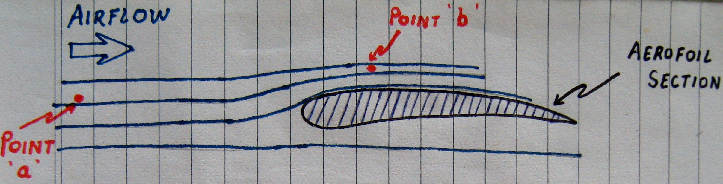
Bernoulii's equation, considering the two points '' and '
' in the airflow (refer Diagram 2), is given by:
where,
and
is the Pressure of the fluid at Point
and
respectively
and
is the Velocity of the fluid at Point
and
is the vertcal elevation at Point
is the Density of the fluid
is the acceleration due to gravity
For our calculation, we shall consider the values of and
to be constant at both points
and
. We shall also assume the values of
and
to be negligible in a wind tunnel experiment. The equation can then be written as:
Since is at a point in the airflow that is unaffected by the passage of the aerofoil through the air, the values of pressure and velocity at this point can be considered to be the same as that of ambient air.
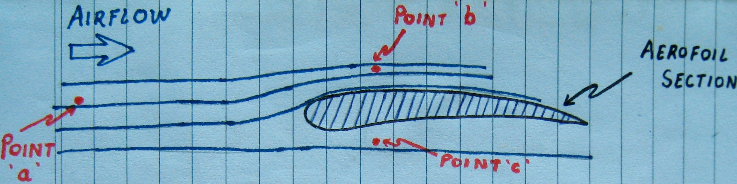
Now consider a Point (Diagram 3 above ) that is located below the aerofoil section.
Using Bernoulli's equation from (#1), equating the values of pressure and velocity at this point () with those of ambient air, we get:
From Eq (#2) and (#3) we have:
According to the Kutta condition of circulation, the airflow over the upper surface of the aerofoil is faster than that below the underside of the aerofoil.
i.e.
Therefore, to satisfy the condition given in Eq(#4),
The net result is an upward acting force which is termed as 'Lift'.
Forces acting in Flight
In the following diagram, we see four forces acting on an aircraft at all times.
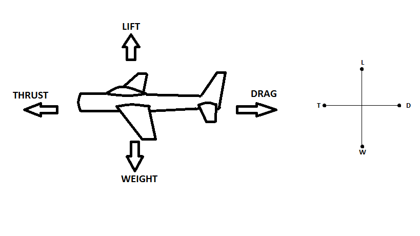
When an aircraft is in level flight, all the four fources are balanced and the aircraft can be said to be in a state of Equilibrium.
Lift() = Weight(
), and
Thrust() = Drag(
)
In such state the aircraft will be travelling at a steady height, at a uniform velocity, and fixed heading.
Climbing and Descending
The following discussion explains the relationship between these four forces when an aircraft is in the phase of gaining altitude (climbing), and when the aircraft descends.
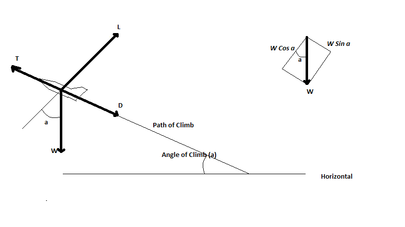
In the above diagram, consider the angle of climb to be .
Resolving the vectors about , we get:
- component
directly opposing Thrust
; and,
- component
directly opposing Lift
.
Therefore,
Implying that in a climb,
Also,
Implying that
(It is important to note the definition of Lift in this context)
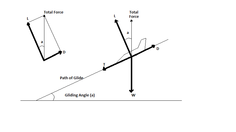
In the above diagram, consider the angle of descent to be .
Resolving the vectors we find that the Total Force, acting equal and opposite to the weight (), is a resultant of the Lift
and Drag
vectors. That is,
This implies that
Or,
Higher the value of the ratio , the flatter the gliding angle - the more appropriate (for man and machinery) the descent from altitude.
Note : As we shall see in a later section, the ratio of L and D also has a significant effect on the Range and the Endurance(in other words the Performance) of the aircraft.
Note regarding Numericals In working out numericals associated with the Forces in Flight, it is important to note that the vectors (,
,
,
) are merely representative, and do not indicate their actual position. This is further explained in the diagram below.
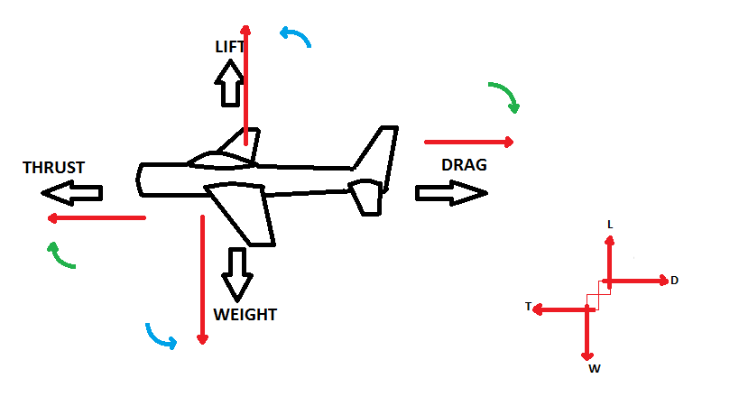
In low wing aircrafts, the vector is often located ahead of the
vector; providing a couple with a nose-down pitching moment. Similarly, and directly opposing this (
-
) couple, the
vector is located below the
vector; providing a couple with a nose-up pitching moment.
Note: In the event of loss of power (),the nose-down pitching moment takes precedence, allowing the aircraft to enter into a glide. If a nose-up pitching moment was provided in such an event, the aircraft would inevitably stall and descend uncontrollably earthward. Thus the need for Weight and Balance of an aircraft, and the need to ensure that the C of G is within limits. This will be further analysed in future pages.
In addition,the forces acting on the Mainplane (Wings) are balanced by similar forces acting on the Tailplane (Stabilizer). All such numericals can be solved withe reference to the law of moments.
Example 1
A seaplane of mass 20000 Kg. is flying in Straight and Level Flight. The thrust vector is located 1.2m ABOVE the drag vector. If the Lift/Drag ratio is 5:1, calculate the position of the lift vector. Consider the forces on the tail plane to be absent or negligable. Assume
By resolving the vectors it can be seen that in this case the Thrust and drag vectors produce a nose-down pitching moment. To oppose this, the Lift and Weight vectors will produce a nose-up pitching moment, i.e. Lift vector ahead of weight.
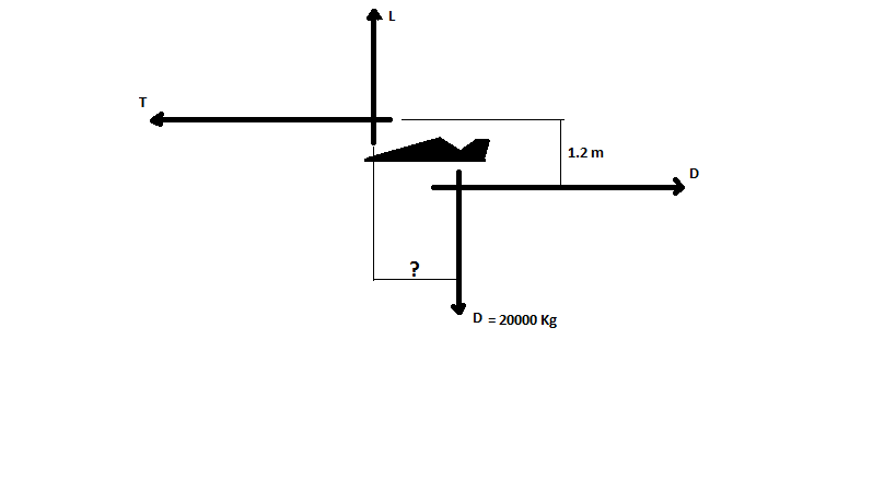
Let be the moment arm between
and
In st. and level flight we know,
=
= 20000g kN
ratio = 5:1
Therefore, = 4000g kN =
Resolving the moments we get,
= 0.24m
The Lift vector is positioned 0.24m ahead of the Weight vector.
Example 2
A training aircraft with a mass of 1854Kg. is on a routine cross country flight cruising in straight and level attitude. The engine is producing a thrust of 4kN, the thrust vector being 180mm below the drag vector. The tail plane is located 5.8m behind the Centre of Gravity of the airplane, and the Lift and weight vectors are separated by 85mm. Calculate:
- What force must there be on the tail plane if the aircraft is to continue in straight and level flight?
- If the Lift and weight vectors shifted in flight to be positioned directly overhead each other, what would be the new force on the tail plane?
Assume
Consider the lift on the mainplane to be = , and the lift on the Tailplane =
. From the Diagram alongside it can be seen that total Lift:
However, in straight and level flight,
=
= (1854 * 9.81)N or, 181.88kN
Considering moments about point O (the intersection of the thrust and weight lines):
Nose Up Pitching moments
=
Nose Down Pitching moments
Note that and
will have no moments about O.
Equating the two:
Dividing throughout by 0.085
or,
From (#1) we know
In part two of the problem, and
act along the same line. Therefore,
Nose Up Pitching moments
=
Nose Down Pitching moments
Equating:
The tail plane will need a Downward (negative) force of 2.57kN for the aircraft to maintain a straight and level attitude.
In the second part, when the Lift and Weight vectors shift to act along the same line, an Upward force of 123.7N will be necessary to maintain level flight.
Example 3
A commercial jet climbs out of an airfield with an airspeed of 100knots inclined at an angle of 12 degrees to the horizontal. If the mass of the aeroplane is 12500Kgs., and the drag produced in the climb is 38kN, calculate the thrust and power needed to overcome the drag. [Consider the thrust vector to be parallel to the drag vector.] Assume and
= 12500 * 9.81 = 122.6kN
Thrust necessary
We know that in a climb:
Plugging in the values,
Power necessary
Now Airspeed = 110knots
Converting to m/s:
110 knots = 203.72 km/hr = 56.6 m/sec
To overcome 38kN of drag at an airspeed of 56.6m/sec,
Power needed =
The Thrust necessary to overcome drag is 63.5kN, while the power to overcome drag is 2151kW.