
Lock Gate
Water pressure on Lock Gates
You're viewing an older version of this page (#4210). View the current version.
Whenever a dam or a weir is constructed across a river or canal, the water levels on both the sides of the dam will be different. If it is desired to have navigation or boating in such a river or a canal, then a chamber, known as lock, is constructed between these two different water levels. Two sets of gates (one on the upstream side and the other on downstream side of the dam) are provided as shown in fig - 1.
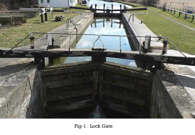
In order to transfer a boat from the upstream (i.e., from a higher water level to the downstream), the upstream gates are opened (while the downstream gates are closed) and water level in the chamber rises up to the upstream water level. The boat is then admitted in the chamber. Then upstream gates are closed and downstream gates are opened and the water level in the chamber is lowered to the downstream water level. Now the boat can proceed further downwards. If the boat is to be transferred from downstream to upstream side, the above procedure is reversed.
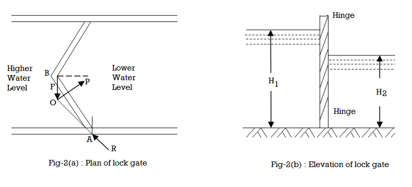
Now consider a set of lock gates AB and BC hinged at the top and bottom at A and C respectively as shown in fig - 2(a). These gates will be held in contact at b by the water pressure, the water level being higher on the left hand side of the gates as shown in fig - 2(b).
Let,
- P = Water pressure on the gate AB or BC acting at right angles on it
- F = Force exerted by the gate BC acting normally to the contact surface of the two gates AB and BC (also known as reaction between the two gates), and
- R = Reaction at the upper and lower hinge
Since the gate AB is in equilibrium, under the action of the above three forces, therefore they will meet at one point. Let, P and F meet at O, then R must pass through this point.
Let, = Inclination of the lock gate with the normal to the walls of the lock.
From the geometry of the figure ABO, we find that it is an isosceles triangle having its angles OBA and
OAB both equal to
.
and now resolving the force at right angles to AB
Now let us consider the water pressure on the top and bottom hinges of the gate, Let,
- H\_1 = Height of water to the left side of the gate.
- A\_1 = Wetted area (of one of the gates) on left side of the gate
- P\_1 = Total pressure of the water on the left side of the gate
- H\_2, A\_2, P\_2 = Corresponding values for right side on the gate
- R\_T = Reaction of the top hinge, and
- R\_B = Reaction of bottom hinge
Since the total reaction (R) will be shared by the two hinges (R\_T), therefore
and total pressure on the lock gate,
Similarly,
Since the directions of P\_1 and P\_2 are in the opposite direction, therefore the resultant pressure,
We know that the pressure P\_1 will act through its center of pressure, which is at a height of from the bottom of the gate. Similarly, the pressure P\_2 will also act through its center of pressure which is also at a height of
from the bottom of the gate.
A little consideration will show, that half of the resultant pressure (i.e., P\_1 - P\_2 or P)will be resisted by the hinges of one lock gate (as the other half will be resisted by the other lock gates).
where h is the distance between the two hinges.
Also resolving the forces horizontally,
From equations (#4) and (#5) the values of R\_B and R\_T may be found out.
Example 1 [metric]
Two lock gates of 7.5m height are provided in a canal of 16m width meeting at an angle of . Calculate the force acting on each gate, when the depth of water on upstream side is 5m.
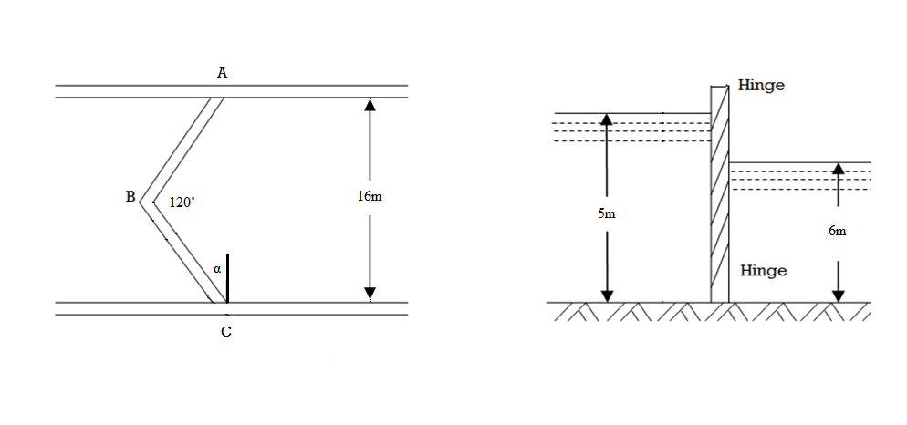
Given,
- Height of lock gates = 7.5m
- Width of lock gates = 16m
- Inclination of gates =
- H = 5m
From the geometry of the lock gate, we find that inclination of the lock gates with the walls,
and width of each gate = =
= 9.24 m
Wetted area of each gate,
and force acting on each gate,
Force acting on each gate, P = 1133 KN
Example 2 [metric]
The locks of a gate 10m wide make an angle of when closed. The water levels on the upstream and downstream sides are 6m and 4m respectively as shown in figure.
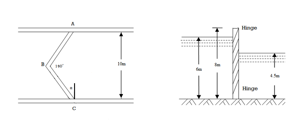
Each gate is carried out by two hinges placed at the top and bottom of the gate. Find (i) resultant force on each gate, and (ii) force acting on each hinge.
Given,
- Width of lock gate = 10 m
- Angle which the gates make when closed,
- H\_1 = 6 m
- H\_2 = 4.5 m
- Distance between the hinges, h = 8 m
(i) Resultant force on each gate
From the geometry of the lock gate, we find that the inclination of the lock gates with the walls,
and width of each gate
Wetted area of each gate on the upstream side,
Wetted area of each gate on the downstream side,
We know that the force acting on each gate on the upstream side,
The force acting on each gate on the downstream side,
Resultant force on each gate,
(i) Force acting on each hinge
Let,
- R\_T = Force acting on the top hinge, and
- R\_B = Force acting on the bottom hinge
We know that reaction between the gates,
We also know from the equation of forces acting on the hinges that,
Resultant force on each gate = 411 KN
Force acting on top hinge = 198.5 KN
Force acting on bottom hinge = 402.4 KN