Curved Beams
An analysis of stresses and strains in curved beams
You're viewing an older version of this page (#3358). View the current version.
Stress in bars of small initial curvature.
Where the radius of curvature is large compared to the dimensions of the cross section, the analysis of stress is similar to that for pure bending.
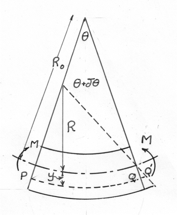
Let be the initial ( unstrained) radius of curvature of the neutral surface and R the radius of curvature under the action of a pure bending moment M
Then the strain in a n element at a distance y from the neutral axis is given by:-
since
If y is neglected in comparison with
Neglecting lateral stress the normal stress
substituting in equation (4)
Total normal stress = 0
which shows that the neutral axis passes through the centroid of the section.
Combining equations (6)and(10)
the strain energy of a short length (measured along the neutral surface) under the action og bending moment M is:-
From equation ( 7)
Application to the design of a piston ring
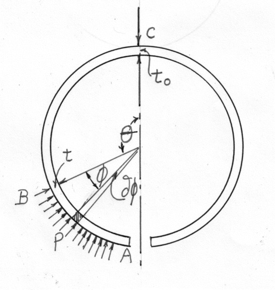
Suppose it is required to design a split ring so that its outside surface will be circular in both the stressed and unstressed conditions and the radial pressure exerted will be uniform. If p is the uniform pressure on the outside then the bending moment at be is given by:-
where d is the depth of the ring in the axial direction integrating
Which is the required variation of thickness Using equation (16). The maximum bending stress at any section
which has it's greatest value when
which determines the initial radius when values for are assumed.
Stresses in Bars of Large Initial Curvature.
When the radius of curvature is of the same order as the dimensions of the cross section, it is no longer possible to neglect y in comparison to R and it will be found that the neutral axis does not pass through the centroid. Further the stress is NOT proportional to the distance from the neutral axis
where y is the distance from the neutral axis as before and is the initial d radius of the neutral surface.
For pure bending the Total normal force on the cross section = 0
Where e is the distance between the neutral axis and the principle axis which is through the centroid ( e is positive when the neutral axis is on the same side of the centroid as the centre of curvature)
Substituting in equation (30)
Rearranging
In this equation y is positive measured outwards, a positive bending moment being one that tends to increase the curvature.
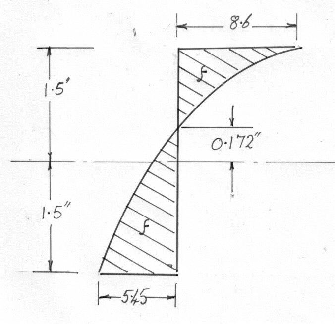
Rectangular Cross-section
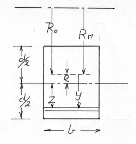
from equation (28)
Let z = y - e = the distance from the centroid. Also the mean radius of curvature
As e is small compared to and d, itis difficult to calculate with sufficient accuracy from this equation and the expansion of the log term into a convenient series is of advantage.
then
Example 1
Trapezoidal Cross-section.
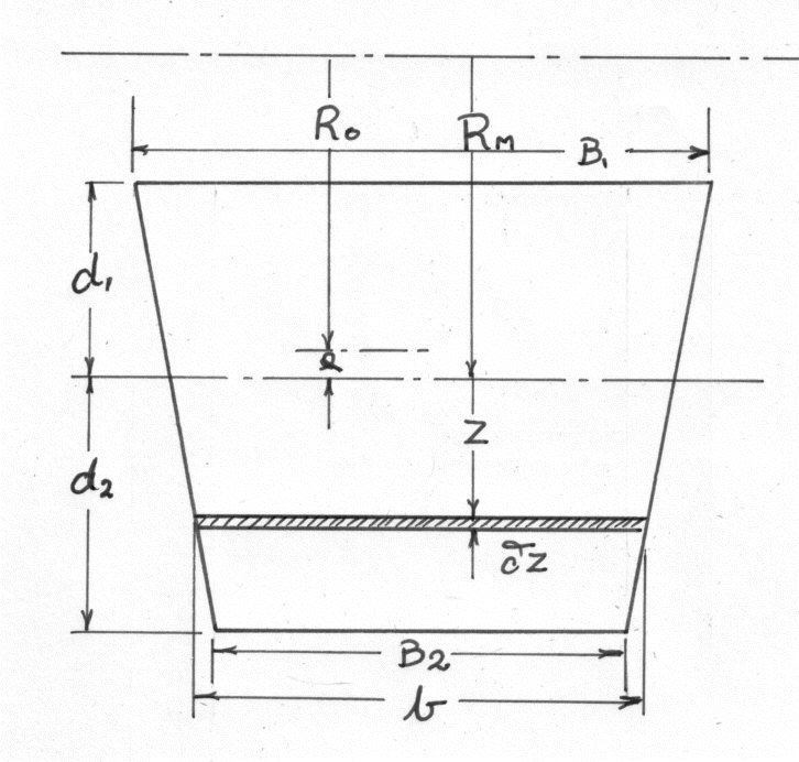
By Moments
By putting
from which
and since
Example 2
Circular Cross section
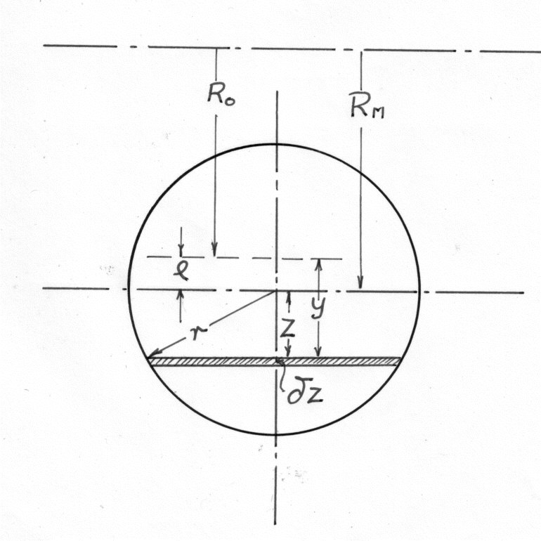
The analysis follows the same method as was used in the previous section on Trapezoidal cross sections.
To evaluate the above expand
Deflection of Curved Beams (Direct Method)
If the length of an initially curved beam is acted upon by a bending moment M it follows from equation (10) that;-
But is the change of angle subtended by
at the centre of curvature and consequently is the angle through which the tangent at one end of the element rotates relative to the tangent at the other end.
i.e.
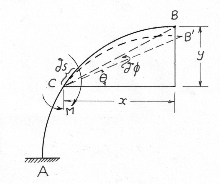
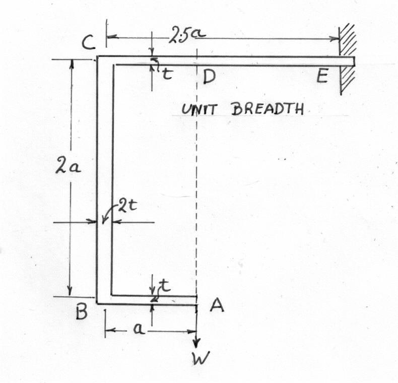
The diagram shows a loaded bar which is fixed in direction at A and it is required to find the deflection at the other end B
Due to the action of M on at C only, the length CB is rotated through an angle
The vertical deflection of B = BB' cos
The horizontal deflection of B = BB' sin
Due to the bending of all the elements along AB
The vertical deflection at B
And the horizontal deflection =
Example 3
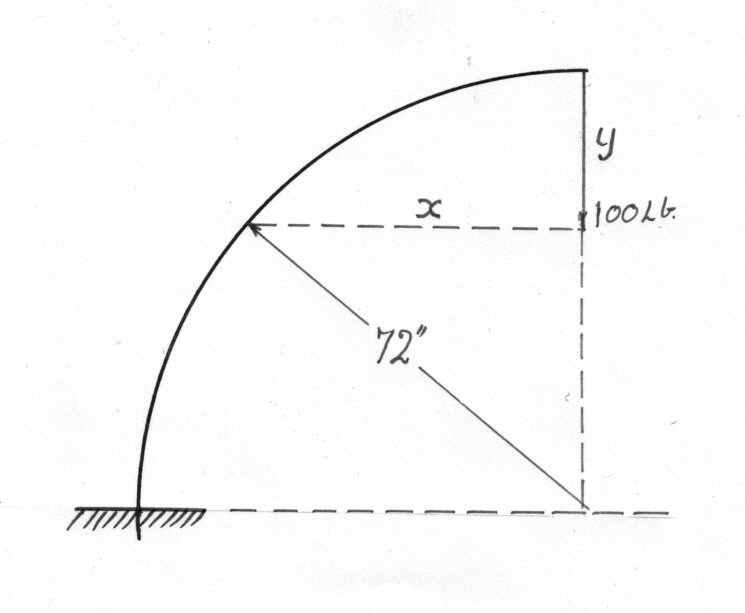
Deflection from Strain Energy ( Castigliano's Theorem)
Theorem If U is the total strain energy of any structure due to the application of external loads
and to the couples ...then the deflections at
...in the directions
... are
and the angular rotations of the couples are
at their applied points.
Proof for concentrated loads
If the displacements ( in the directions of the loads) produced by gradually applied loads
Let alone be increased by
then
where
But if the loads
Subtracting equation ( 108 ) and neglecting the products of small quantities
Subtracting equation ( 110 )
Similarly for and the proof can be extended to incorporate couples.
It is important to stress that U is the total strain energy, expressed in terms of loads and not including statically determinate reactions and the partial derivative with respect to each load in turn ( treating the others as constant) gives the deflection at the load points in the direction of the load.
The following principles should be observed in applying the theorem
- 1) In finding the deflection of curved beams and similar problems, only strain energy due to bending need normally be taken into account(115)
- 2) Treat all loads as variables initially carry out the partial differentiation and integration and only putting in numerical values at the final stage.
- 3) If the deflection is to be found at a point where, or in a direction there is no load, a load may be put in where required and given a value of zero in the final reckoning
Generally it will be found that the strain energy method requires less thought in application than the direct method, it being only necessary to obtain an expression for the bending moment; also there is no difficulty over the question of sign as the strain energy is bound to be positive and deflection is positive in the direction of the load. The only disadvantage occurs when a case such as mentioned in note 3 above has to be dealt with in which case the direct method will probably be shorter.