Aerofoil and Euler theories applied to Axial Pumps and Fans.

You're viewing an older version of this page (#3365). View the current version.

View versions (5)

Axial Flow Pumps and fans.

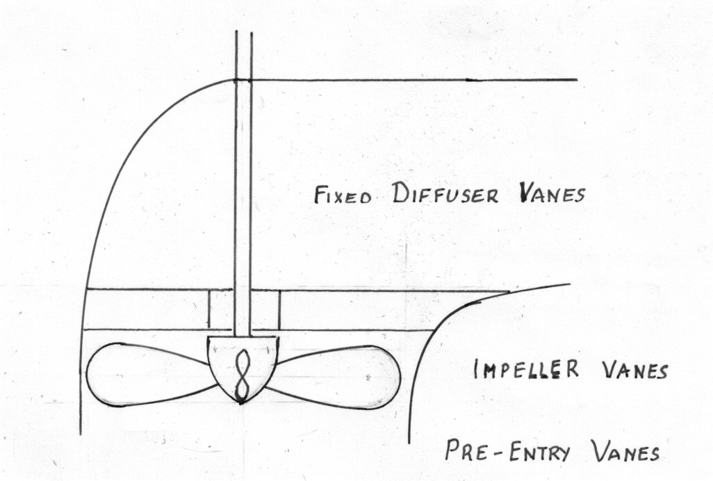
13108/img_axf1.jpg
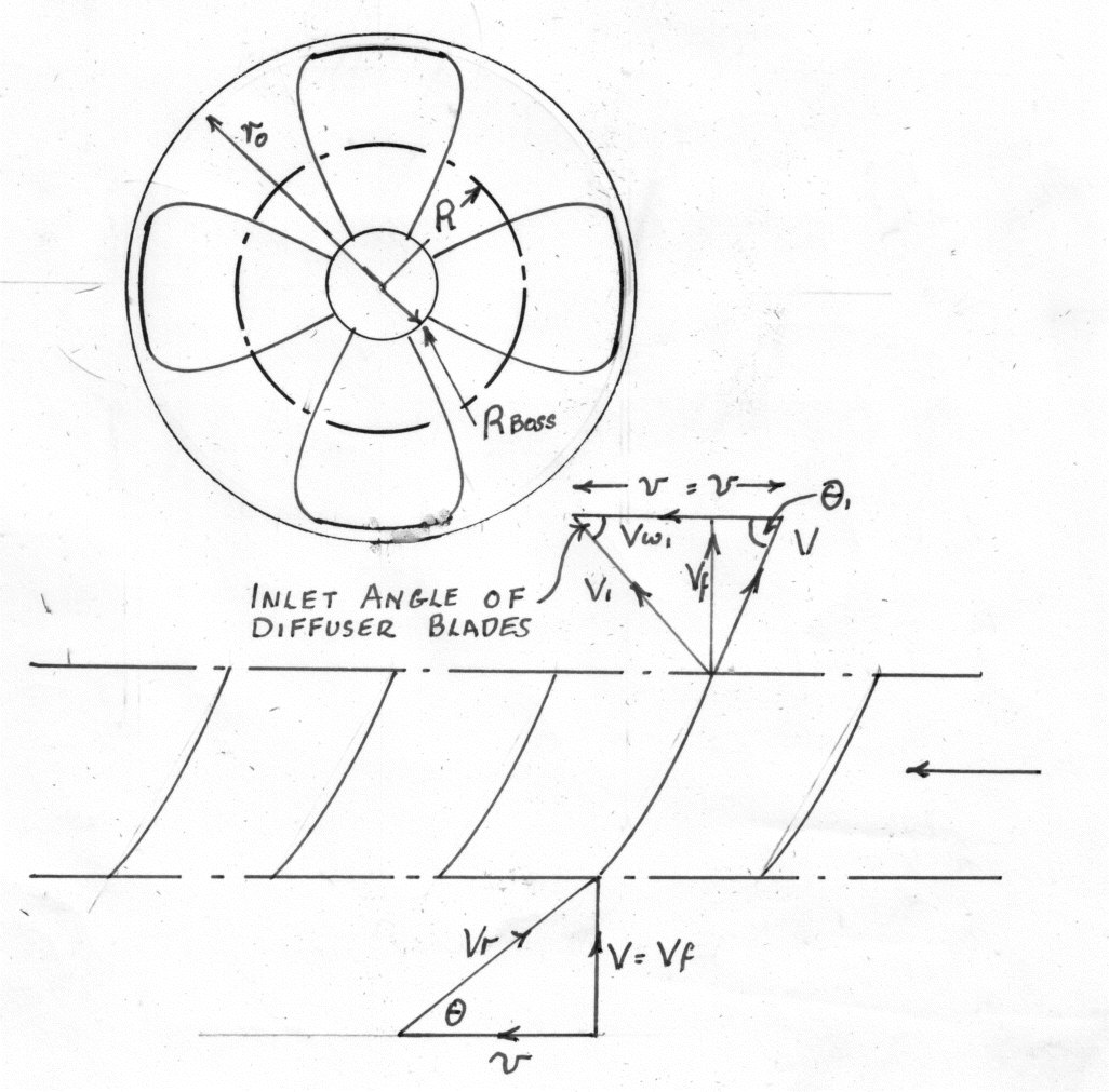
13108/img_axf2.jpg

Notes 1) The fixed diffuser vanes are used to remove the whirl component of the discharge velocity of the impeller and to convert the energy to Pressure.

2) The impeller vanes may be adjustable

3) The machine may be fitted with pre-entry vanes to ensure that there is no pre-rotation and that the flow is purely Axial.

4) The bottom diagram is produced by considering a Radius R of the impeller and drawing it out in a flat plane.

Blank
v_1 = v = \frac{2\pi RN}{60}
(1)

The flow through the machine, q = \pi \left(r_0^2 - r_{boss}^2 \right)\times V_f. The boss area can be neglected.

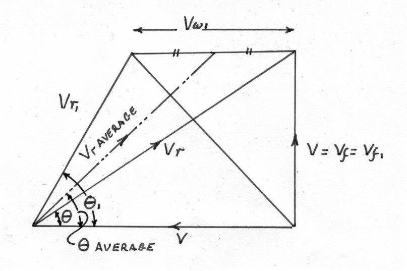
Also\;\;\;\;\;V = V_f = V_f1\;\;\;\;( Blade\;area\;neglected)
(2)
Blank

Euler Theory

Work done by the Vanes per lb. of water = \frac{V_{w1}v_1 - V_wv}{g} = \frac{V_{w1}v}{g}\;ft. (V_w = 0)

Hydraulic\;or\;Manometric\;\eta  = H_m\div \frac{V_{w1}v}{g}
(3)

Where H_m = The Manometric head minus the Head developed by the Pump across the Flanges.

Blank

Applying Bernoulli's equation across the Vanes:-

\frac{p}{w} + \frac{V^2}{2g}\;+\frac{V_{w1}v}{g} = \frac{p_1}{w} + \frac{v_1^2}{2g} (Neglecting\;losses\;in\;the\;Vanes)
(4)

Therefore the Pressure rise across the Vanes is given by:-

\frac{p_1 - p}{w} = \frac{V_{w1}v}{g} - \frac{V_1^2 - V^2}{2g}
(5)
But\;\;\;\;\;V_1^2 = V_{w1}^2 + V_{f1}^2 = V_{w1}^2 + V_{f}^2 = V_{w1}^2 + V^2
(6)
\therefore\;\;\;\;\;\frac{p_1 - p}{w} = \frac{V_{w1}v}{g} - \frac{V_{w1}^2}{2g}
(7)

Aerofoil Theory Applied to Propeller Pumps.

The Combined Inlet and Outlet and Inlet Triangles.
Blank
13108/img_axf3.jpg
Blank

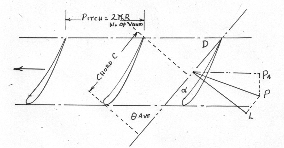
The Blades are considered to be aerofoils in cascade in a fluid stream of Velocity V_r\;Average in a direction \theta to the tangent.

Blank
13108/img_axf4.jpg
Blank

Force P exerted by the Fluid on the Vane element i the vector Sum of the liftL and the force exerted on the Vane by the Fluid. The components of P are P_t in the Tangential Direction and P_a in the Axial Direction.

Consider an elemental Vane thickness dR at Radius R.

From\; Aerofoil\; Theory \;Lift\;(L) = C_L\;\times \;\frac{1}{2}\rho V_{r\;ave.}^2\;\times C\;dr\;\;lb.
(8)
And\;\;\;Drag\;(D) = C_D\;\times \;\frac{1}{2}\rho V_{r\;ave.}^2\;\times C\;{dR}\;\;lb.
(9)

C_L\;and\;C_D are lift and drag coefficients depending upon the aerofoil section and the angle of incidence.

Resolving L and D in the direction of motion.

P_t = L\;sin\,\theta _{ave.} + D\;Cos\,\theta _{ave.}\;\;\;\;lb./Vane
(10)
P_a = L\;Cos\,\theta _{ave.} - D\;Sin\,\theta _{ave.}\;\;\;\;lb./Vane
(11)

D is commonly small compared with L and the second terms are often neglected.

For N Vanes the Total Tangential Force = n\;P_t

= n\left(L\;Sin\,\theta _{ave.} + D\;Cos\,\theta _{ave.} \right)
(12)
\therefore\;\;\;\;\;Torque = nP_t\times R
(13)

The Horse-Power required to rotate the Vane elements = \frac{2\pi NT}{33000}

The\; Efficiency \;\eta  = \frac{W.H.P.\;out put}{H.P.\;in put}
(14)

Where W = Weight of flow through the annular ring = w\times 2\,\pi\;RdR \times V_f

The Total Axial Force = n Pa

If \Delta p is the pressure drop across the vanes

\Delta p\times 2\pi \,R\,dr = nP_a
(15)

This equation can be solved to find \Delta p

Example 1

The figures below are for an Axial Flow Propeller fan pumping air. It is required to find the torque /ft. radius using both Aerofoil and Euler Theories.

Radius R = 3.2 ft. Speed N = 450 r.p.m.

V = V_f = V_{f1} = 131\;ft./sec
(16)
V = V_f = V_{f1} = 131\;ft./sec\;\;\;\;\;and\;\;\;\;\;\rho  = 0.074\;lb/ft^3
(17)

Theoretical Head = 114 ft. of air.

\eta _H = 0.9\;\;\;\;\;\;\;\;\;\;\;\;\;\;n = 12\;Vanes
(18)
C_L = 0.44\;\;\;\;\;\;\;\;\;\;\;\;\;\;\;C_d = 0
(19)

Chord = 1.1 ft.

It is required to find the Torque per ft radius

\eta _H = H_M\div \frac{V_{w1}V_1}{g} = 114\div \frac{V_{w1}v_1}{g}
(20)
But\;\;\;\;\;v_1 = v = \frac{2\pi RN}{60} = 151\;ft./sec.
(21)
\therefore\;\;\;\;\;V_{w1} = \frac{114\times 32.2}{0.9\times 151} = 27\;ft./sec.
(22)

Velocity triangle.

V_{r\, ave.} = 131^2 + (151 - 13.5)^2 = 190\;ft./sec.
(23)
\theta _{ave.} = Tan^{-1}\frac{131}{151 - 13.5} = 43^0\;36'
(24)
lift = C_L\times \frac{1}{2}\rho V_{r\,ave.}\times C\times dR
(25)
= 0.44\times \frac{0.074}{2\times 32.2}\times 190^2\times 1.1\;lb./ft.radius
(26)
= 20.1 lb./ft radius
(27)
P_t = 20.1\times Sin\theta _{ave.} = 13.85\;lb./ft. Radius
(28)

For twelve Vanes the longitudinal Force = 12 Pt

Blank
\therefore\;\;\;\;\;Torque\;required = 12\;P_t\;R
(29)
= 12\times 13.85\times 3.2 = 532\'lb.ft./ft.\,Radius
(30)
Blank

NOTE

Axial thrust / blade P_a = L\,cos\,\theta _{ave.}

= 20.1\times Cos\,45^0\;36' = 14.55\;lb./ft.\;width
(31)

Total axial Force for 12 Vanes = 14.55 X 12 = 174.6 lb./ft. width

If \delta\,p is the pressure rise

Then\;\;\;\;\;\Delta p\times 2\pi \times  R\,dR = 174.6 lb./ft.
(32)
\therefore\;\;\;\;\;\Delta p = \frac{174.6}{2\pi \times 3.2} = 8.68\;lb./ft^2
(33)
or\;\;\;\;\;\Delta p = \frac{8.68}{0.074} = 117.3\;ft.\;of\;air
(34)

The above question can also be done using the Euler Theory.

The weight of Flow through an annular element (W ) = 2\pi \;R\,dR\times V_f\times w

= 2\times 3.2\times \pi \times 1\times 131\times 0.074 = 195\;lb./sec.
(35)

Work done per lb per lb. = \frac{V_{w1}v_1}{g} = \frac{H_M}{\eta }

= \frac{114}{0.9} = 126.7\;ft.lb./lb.
(36)

Therefore the work done per second per ft. radius

= W\times \frac{V_{w1}v_1}{g} = 195\times 126.7\;ft.\;lb.\;/sec.
(37)
= Torque\times Angular\;Velocity = \frac{T\times 2\pi N}{60}
(38)
\therefore\;\;\;\;\;T = \frac{195\times 126.7\times 60}{2\times \pi \times 450} = 524\;lb.ft.
(39)

The Pressure rise across the Vanes:-

\frac{p_1 - p}{w} = \frac{V_{w1}v_1}{g} - \frac{V_{w1}^2}{2g}
(40)
= 126.7 - \frac{27^2}{64.4} = 115.4 \;ft.\; of\; air
(41)