
Axial Flow Pumps and Fans
Leonhard Euler (15 April 1707 - 18 September 1783) was a pioneering Swiss mathematician and physicist. He made important discoveries in fields as diverse as infinitesimal calculus and graph theory.
Torque, also called moment or moment of force, is the tendency of a force to rotate an object about an axis, fulcrum, or pivot. Just as a force is a push or a pull, a torque can be thought of as a twist.
Aerofoil and Euler theories applied to Axial Pumps and Fans.
You're viewing an older version of this page (#3815). View the current version.
Axial Flow Pumps and fans.
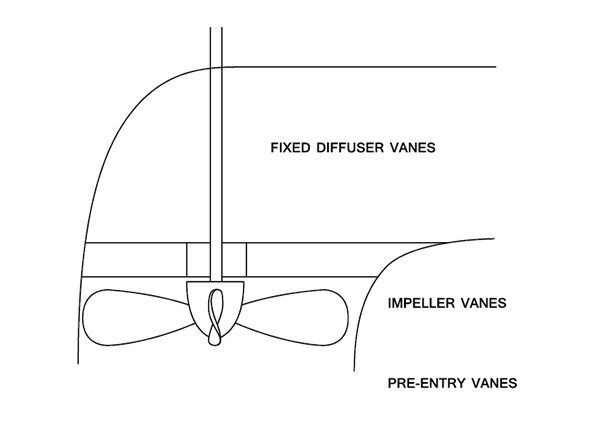
The figures below are for an Axial Flow Propeller fan pumping air.
Notes:
- The fixed diffuser vanes are used to remove the whirl component of the discharge velocity of the impeller and to convert the energy to Pressure.
- The impeller vanes may be adjustable
- The machine may be fitted with pre-entry vanes to ensure that there is no pre-rotation and that the flow is purely Axial.
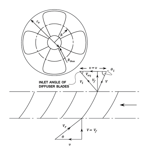
- The bottom diagram is produced by considering a Radius
of the impeller and drawing it out in a flat plane.
The flow through the machine, . (The boss area can be neglected.)
Also, (Blade area neglected.)
Euler Theory
Work done by the Vanes per lb. of water (
)
Hydraulic or Manometric
Where = The Manometric head minus the Head developed by the Pump across the Flanges.
Applying Bernoulli'\b{s equation} across the Vanes: (Neglecting losses in the Vanes)
Therefore the Pressure rise across the Vanes is given by:
But,
Aerofoil Theory Applied to Propeller Pumps.
The Combined Inlet and Outlet and Inlet Triangles.

The Blades are considered to be aerofoils in cascade in a fluid stream of Velocity Average in a direction
to the tangent.
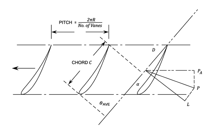
Force exerted by the Fluid on the Vane element i the vector Sum of the lift L and the force exerted on the Vane by the Fluid. The components of P are
in the Tangential Direction and
in the Axial Direction.
Consider an elemental Vane thickness at Radius
.
From Aerofoil Theory Lift,
And Drag,
and
are lift and drag coefficients depending upon the aerofoil section and the angle of incidence.
Resolving and
in the direction of motion.
is commonly small compared with
and the second terms are often neglected.
For Vanes the Total Tangential Force =
Therefore, Torque
The Horse-Power required to rotate the Vane elements =
The Efficiency, = W.H.P. out put / H.P. in put
Where W = Weight of flow through the annular ring =
The Total Axial Force = If
is the pressure drop across the vanes,
This equation can be solved to find .
Example 1 [imperial]
For the Axial Flow Propeller it is required to find the torque /ft. radius using both Aerofoil and Euler Theories.
We know the radius is
and the speed
is
and
Theoretical Head = 114 ft. of air.
Vanes
Chord = 1.1 ft.
It is required to find the Torque per ft radius
But,
Velocity triangle:
For twelve Vanes the longitudinal Force = 12 Pt
Therefore, Torque required
Note:
Axial thrust / blade
Total axial Force for 12 Vanes =
If is the pressure rise, then
Or,
\subsection{An alternative approach is:} The weight of Flow through an annular element,
Work done per lb per lb.
Therefore the work done per second per ft. radius
= Torque * Angular Velocity =
The Pressure rise across the Vanes:
The Torque required is
The above question can also be done using the Euler Theory.
The weight of Flow through an annular element,
Work done per lb per lb.
Therefore the work done per second per ft. radius
= Torque * Angular Velocity =
The Pressure rise across the Vanes: