The deflection of Continuous Beams with more than one span.

You're viewing an older version of this page (#3523). View the current version.

View versions (4)

Continuous Beams

When a Beam is carried on three or more supports it is said to be Continuous. It is possible to use an extension of the Moment-Area method ( See "Bending of Beams Part 3") to obtain a relationship between the Bending Moments at three points ( Usually Supports.)
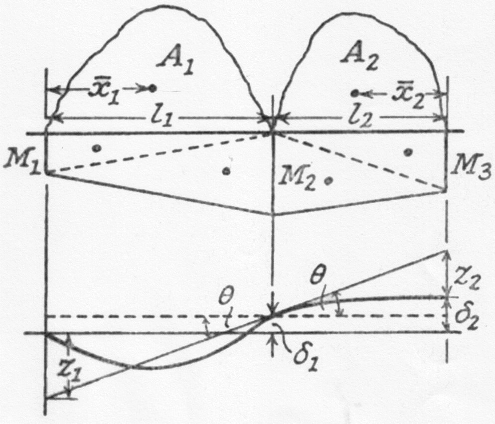
13108/img_cb_108.jpg

On the drawing the areas \displaystyle A_1\;\;and\;\;\;A_2 are the Free Bending Moment areas obtained by treating the Beam as over two separate spans \displaystyle l_1\;\;and\;\;\;l_2 . If the actual Bending Moments at these points are \displaystyle M_1\;;\;\;M_2\;\;\;and\;\;\;M_3. Then a Fixing Moment diagram consisting of two trapezia can be introduced and the actual Bending Moment will be the Algebraic sum of the two diagrams.

In the lower figure the Elastic Line of the deflected Beam is shown. The deflections \displaystyle \delta _1\;\;and\;\;\delta _2 are measure relative to the left hand support and are positive upwards. \displaystyle \theta is the slope of the beam over the central support and \displaystyle Z_1\;\;\;and\;\;\;Z_2 are the intercepts for \displaystyle l_1\;\;\;and\;\;\;l_2

\therefore\;\;\;\;\;\;\theta \;=\;\frac{Z_1\;+\;\delta _1}{l_1}\;=\;\frac{Z_2\;+\[\delta _2\;-\;\delta _1}{l_2}
(1)

Note. This assumes that the slopes everywhere are small.

\frac{A_1\bar{x}_1\;-\;(M_1 l_1/2)(2\;l_1/3)\;-\;(M_2l_1/2)(2\;l_1/3)}{E\;I}\;+\;\frac{\delta _1}{l_1}
(2)
\;\;\;\;\;\;\;=\;-\;\frac{A_2\bar{x}_2\;+\;(M_3 l_2/2)(2\;l_2/3)\;+\;(M_2l_2/2)(2\;l_2/3)}{E\;I}\;+\;\frac{\delta _2\;-\;\delta _1}{l_1}
(3)

Note that \displaystyle Z_2 is a negative intercept.

The above equation can be written as:-

\frac{M_1\;l_1}{I_1}\;+\;2M_2\left(\frac{l_1}{I_1}\;+\;\frac{l_2}{I_2} \right)\;+\;\frac{M+3\;l_2}{I_2}\;
=\;6\left(\frac{A_1\bar{x}_1}{I_1\;l_1}\;+\;\frac{A_2\;\bar{x}_2}{I_2\;l_2} \right)\;+\;6E\;\left[\left(\frac{\delta _1}{l_1}\right)\;+\;\left(\frac{\delta _1\;-\;\delta _2}{l_2} \right) \right]
(4)

If \displaystyle I_1\;=\;I_2

M_1\;l_1\;+\;2M_2(l_1\;+\;l_2)\;+\;M_3\;l_2\;=\;6\left(\frac{A_1\bar{x}_1}{l_2} \right)\;+\;6\;E\;I\left[ \frac{\delta _1}{l_1}\;+\;\frac{\delta _1\;-\;\delta _2}{l_2}\right]
(5)

If the supports are at the same level:-

\mathbf{M_1\;l_1\;+\;2M_2( l_1 \;+\;l_2)\;+\;M_3\;l_2\;=\;6\left(\frac{A_1\bar{x}_1}{l_2} \right)\;+\;6\;E\;I\left(\frac{A_1\bar{x}_1}{l_1}\;+\;\frac{A_2\;\bar{x}_2}{l_2} \right)}
(6)

If the Ends are Simply Supported then \displaystyle M_1\;=\;M_3\;=\;0

M_2(l_1\;+\;l_2)\;=\;3\;\left(\frac{A_1\;\bar{x}_1}{l_1}\;+\;\frac{A_2\;\bar{x}_2}{l_2} \right)
(7)

Clapeyron's Equation or The Equation of Three Moments

Equation (4) is the most general form of The Equation of Three Moments. Equations (5) (6) and (7) are simplifications to meet particular needs. Of these Equation (6) is the form most frequently required.

Example 1

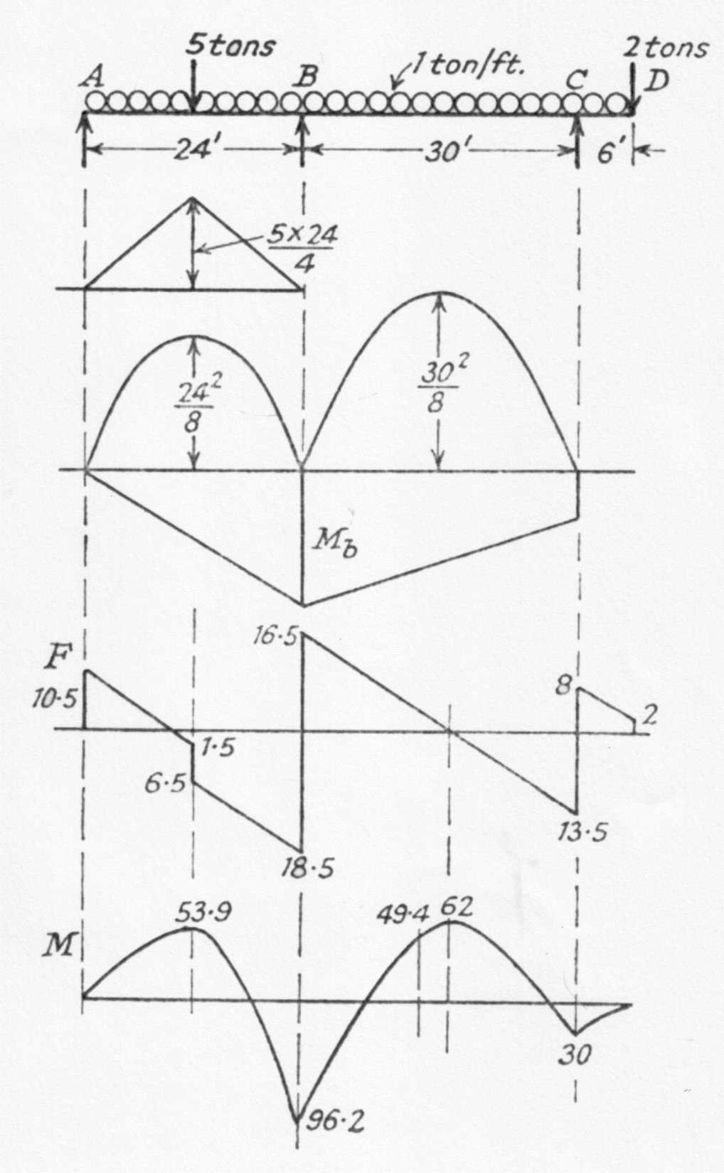
A Beam Ad 60 ft. long rests on supports at A, B, and C which are at the same level. AB = 24 ft. and BC = 30 ft. The loading is 1 ton/ft. throughout and in addition a concentrated load of 5 tons acts at the mid-point of AB and a load of 2 tons acts at D Draw the Shear Force and Bending Moment diagrams.

M_a\;=\;0
(8)
M_c\;=\;2\times6\;+\;6\times3\;=\;30\;tons-ft.
(9)

Applying Equation (6) to the span A B C

2M_b\times 54\;+\;30\times30\;=\;6\left[\left(\frac{1}{2}\times\frac{5\times24}{4}\times24 \right)\times\frac{12}{24}\;+\;\left(\frac{2}{3}\times\frac{24^2}{8}\times24 \right)\times\frac{12}{24}\;
+\;\left(\frac{2}{3}\times\frac{30^2}{8}\times30 \right)\times\frac{15}{30} \right]
(10)
=\;6\times1881
(11)
\therefore\;\;\;\;\;\;\;M_b\;=\;96.2\;tons-ft.
(12)

The Bending Moment at mid-point of AB

=\;5\times \frac{24}{4}\;+\;\frac{24^2}{8}\;-\;\frac{M_b}{2}\;=\;53.9\;tons-ft.
(13)

The Bending Moment at the mid-point of BC

=\;\frac{30^2}{8}\;-\;\frac{1}{2}\left(M_b\;+\;30 \right)\;=\;49.4\;tons-ft.
(14)

To find the reactions at the supports

M_b\;=\;-\;R_a\times 24\;+\;24\times 12\;+\;5\times 12 \;\;\;\;\;for\;A\,B
(15)
M_b\;=\;-\;R_c\times 30\;+\;36\times 18\;+\;2\times 36 \;\;\;\;\;for\;B\,C\,D
(16)
\therefore\;\;\;\;\;\;R_a\;=\;\left(\frac{288\;+\;60\;-\;96.2}{24} \right)\;=\;10.49\;tons\;\;\;\;say \;10.5\;tons
(17)
And\;\;\;\;\;R_c\;=\;\left(\frac{540\;+\;72\;-\;96.2}{30} \right)\;=\;21.5\;tons
(18)
13108/img_cb_109.jpg

By difference

R_b\;=\;60\;+\;5\;+2\;-\;10.5\;-\;21.5\;=\;35\;tons
(19)

From the Shear Force diagram it can be seen that the maximum Bending Moment occurs either at a distance of 13.5 ft. from C where:-

M\;=\;21.5\times 13.5\;-\;\frac{19.5^2}{2}\;-\;2\times19.5\;=\;62\;tons-ft.
(20)

Or at a distance of 10.5 ft. from A where:-

M\;=\;10,5\times 10.5\;-\;\frac{10.5^2}{2}\;=\;55.2\;tons-ft.
(21)

The combined Bending Moment diagram is shown at the bottom of the sketch.

Example 2

A Beam ABC of uniform cross section rests on elastic supports at A B C each support sinking by 1/100 inches per ton of load carried. If AB is 20 ft and BC 16 ft. and the loading is 1/2 tons/ft. find the reactions at the supports and the maximum Bending Moment.
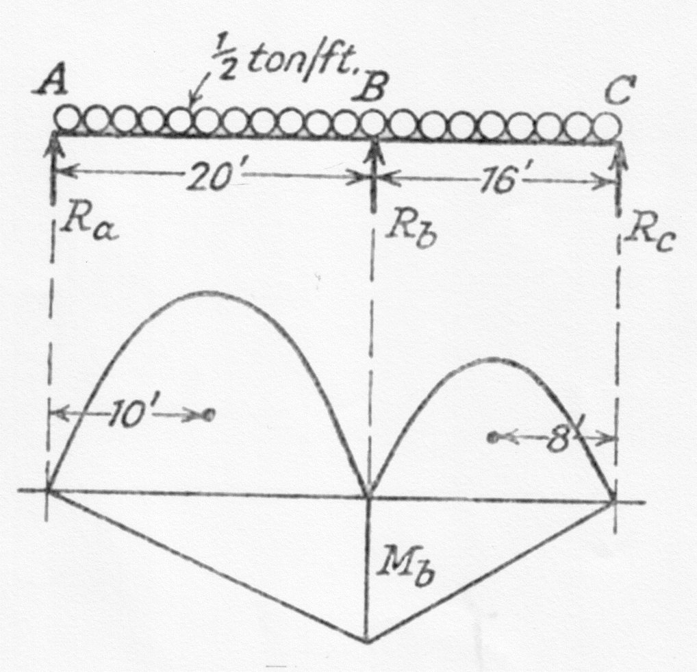
13108/img_cb_110.jpg
E\;=\;13,200\;tons\: in.^{-2}
(22)
I\;=\;1,200\;in^4
(23)

Applying the Theorem of Three Moments . See Equation (5)

M_a\;=\;M_c\;=\;0
(24)
2M_b\times 36\;=\;6\left[\left(\frac{2}{3}\times \frac{20^2}{2\times 8}\times 20 \right)\times\frac{10}{20}\;+\;\left(\frac{2}{3}\times\frac{16^2}{2\times 8}\times16 \right)\times\frac{8}{16}\right]\;+\;6\;E\;I\left[\frac{R_a\;-\;R_b}{100\times 20}\;+\;\frac{R_c\;-\;R_b}{100\times 16} \right]\times\frac{1}{12^3}
(25)
Where\;\;\;\;\;\;\delta _1\;=\;\frac{R_a\;-\;R_b}{100}\;inches
(26)
And\;\;\;\;\;\;\delta _1\;-\;\delta _2\;=\;\frac{R_c\;-\;R_b}{100}\;inches\;upwards
(27)
i.e.\;\;\;\;\;M_b\;=\;21\;+\;0.955\;(4R_a\;-\;9R_b\;+\;5R_c)
(28)

But \displaystyle M_b is th hoggging Bending Moment at B

\therefore\;\;\;\;\;\;M_b\;=\;-\;20\;R_a\;+\;\frac{1}{2}\times \frac{20^2}{2}
(29)
Thus\;\;\;\;\;\;R_a\;=\;5\;-\;\frac{M_b}{20}
(30)
Also\;\;\;\;\;\;M_b\;=\;-\;16\;R_c\;+\;\frac{1}{2}\times \frac{16^2}{2}
(31)
Thus\;\;\;\;\;\;R_c\;=\;4\;-\;\frac{M_b}{16}
(32)
\therefore\;\;\;\;\;\;R_b\;=\;\frac{1}{2}\times 36\;-\;R_a\;-\;R_c\;=\;9\;+\frac{9\;M_b}{80}
(33)

Substituting in equation (28)

M_b\;=\;21\;+\;0.0955\left[20\;-\;\frac{M_b}{5}\;-\;81\;-\[\frac{81}{80}\times M_b\;+\;20\;-\;\frac{5}{16}\times M_b\right]
(34)
\therefore\;\;\;\;\;M_b\;=\;\frac{17.1}{1.142}\;=\;15\;tons-ft.
(35)

From Equation (30) \displaystyle R_a\;=\;4.25\;tons

From Equation (32) \displaystyle R_c\;=\;3.06\;tons

From Equation (33) \displaystyle R_b\;=\;10.69\;tons

The Shear Force is Zero at \displaystyle 4.25\times \frac{1}{2}\;=\;8.5\;ft. from A and at \displaystyle 3.06\times \frac{1}{2}\;=\;6.12\;ft. from C

The Maximum Bending Moment between A and B :-

4.25\times 8.5\;-\;\frac{1}{2}\times\frac{8.5^2}{2}\;=\;18.05\;tons-ft.
(36)

The Maximum Bending Moment between B and C :-

3.06\times 6.12\;-\;\frac{1}{2}\times\frac{6.12^2}{2}\;=\;9.35\;tons-ft.
(37)

Thus the maximum Bending Moment is 18.05 tons-ft.

Beams with more than Two Spans.

Where a Beam extends over more than three Supports the Equation of Three Moments is applied to each group of three in turns. In general if there are n Supports there will be n - 2 unknown Bending Moments ( excluding the Ends) and n - 2 equations to solve simultaneously.

Blank