
The Stresses and Strains generated in a rotating disc or cylinder

You're viewing an older version of this page (#3876). View the current version.

View versions (4)

Discs of Uniform Thickness.

For a "thin" disc it can be assumed that the Stress in the Axial direction is zero. Due to the rotation of the disc, Circumferential \displaystyle f (Hoop) and radial \displaystyle p Stresses will occur. Both these Stresses are Tensile. If the radial shift at a radius r is u, then the Strain Equations are:

E\times \frac{du}{dr} = p - \frac{f}{m}
(1)
And\;\;\;\;\;E\times \frac{u}{r} - \frac{f}{m}
(2)

Differentiating equation (2) and equating it to equation (1) gives:
\left(f - p \right)\left(1 - \frac{1}{m} \right) + r\times \frac{df}{dr} - \left(\frac{r}{m} \right)\left(\frac{dp}{dr} \right) = 0
(3)
23287/Rotating-Discs-and-Cylinders-3-0001.png

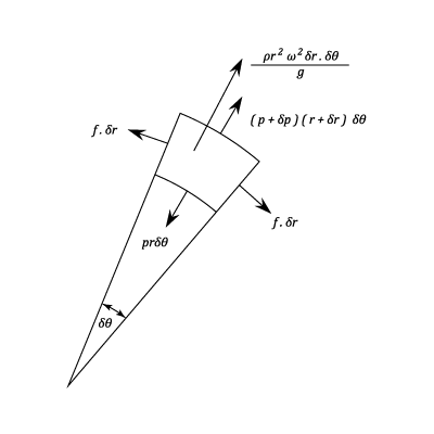
If the angular velocity of rotation is \displaystyle \omega and the density of the disc material is \displaystyle \rho then the element shown in the diagram is subjected to a centrifugal force which:

\left(\frac{\rho r\,\delta \theta \times \delta r}{g} \right)\times r\;\omega ^2
(4)

Which for unit thickness:

\left(\frac{\rho r\,\delta \theta \times \delta r}{g} \right)\times r\;\omega ^2
(5)
= \frac{\rho \,r^2\,\omega ^2\;\delta r\times \delta \theta }{g}
(6)

The equilibrium equation in the radial direction is:

2f\,\delta r\,\sin\frac{1}{2}\,\delta \theta  + \rho r\,\delta \theta  - (p + \delta p)(r + \delta r)\delta \theta  = \frac{\rho \,r^2\,\omega ^2\;\delta r\times \delta \theta }{g}
(7)

In the limit this equation reduces to:

f - p - r\,\frac{dp}{dr} = \frac{\rho \,r^2\;\omega ^2}{g}
(8)

From equation (8) obtain \displaystyle f - p and substitute into equation (3)

\left(r\,\frac{dp}{dr} + \frac{\rho \,r^2\,\omega ^2}{g} \right)\left(1 - \frac{1}{m} \right) + r\times \frac{df}{dr} - \left(\frac{r}{m} \right)\frac{dp}{dr} = 0
(9)

Rearranging

\frac{df}{dr} + \frac{dp}{dr}\;= - \left(\frac{\rho \.r\,\omega ^2}{g} \right)\left(1 + \frac{1}{m} \right)
(10)

Integrating:

f + p\;= - \left(\frac{\rho \,r^2\,\omega ^2}{2g} \right)\left(1 + \frac{1}{m} \right) + 2A
(11)

Subtracting equation (8)

2p + r\,\frac{dp}{dr}= - \left(\frac{\rho \,r^2\,\omega ^2}{2g} \right)\left(3 + \frac{1}{m} \right) + 2A
(12)
\therefore\;\;\;\;\;\frac{1}{r}\;\frac{d(p\,r)^2}{dr}\;= - \frac{\rho \,r^2\,\omega ^2(3 + 1/m)}{2g} + 2A
(13)

Integrating:

p\,r^2\;= - \frac{\rho \,r^4\,\omega ^2(3 + 1/m)}{8g} + 2A\,r^2 - B
(14)
Or\;\;\;\;\;\;\mathbf{p = A - \frac{B}{r^2} - \left(3 + \frac{1}{m} \right)\left(\frac {\rho \,r^2\;\omega ^2}{8g}  \right)}
(15)

Substituting from equation (11)

\mathbf{f = A + \frac{B}{r} - \left(1 + \frac{3}{m} \right)\left(\frac{\rho \;r\;\omega ^2}{8g} \right)}
(16)

A Solid Disc

Since the Stresses can no be infinite at the centre of a solid Disc B must be zero.

If R is the outside radius of the disc then rewriting equations (14) and (15) then:

p = 0 = A - \left(3 + \frac{1}{m} \right)\left(\frac{\rho \,R^2\,\omega ^2}{8g} \right)
(17)

From Which:

p = \left(\frac{\rho \;\omega ^2}{8g} \right)\left(3 + \frac{1}{m} \right)\left(R^2 - r^2 \right)
(18)
And\;\;\;\;\;f = \left(\frac{\rho \;\omega ^2}{8g} \right)\left[ \left(3 + \frac{1}{m} \right)R^2\:-\:\left(1 + \frac{3}{m} \right)r^2  \right]
(19)

At the centre r = 0 and so:

p = f = \left(3 + \frac{1}{m} \right)\left(\frac{\rho \;\omega ^2\,R^2}{8g} \right)
(20)

This is the Maximum Stress.

At the outside :
23287/Rotating-Discs-and-Cylinders-3-0002.png
f = \left(1 - \frac{1}{m} \right)\left(\frac{\rho \,\omega ^2\,r^2}{g} \right)
(21)

For a value of \displaystyle \frac{1}{m} = 0.3

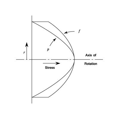
\hat{f} = \left(\frac{3.3}{8} \right)\left(\frac{\rho \,\omega ^2\,R^2}{g} \right) = 0.41\times \frac{\rho \,\omega ^2\,R^2}{g}\;\;\;\;(At\;the\;centre)
(22)

And at the outside:

f = \frac{0.7}{4}\times \frac{\rho \,\omega ^2\,R^2}{g} = 0.425\;\hat{f}
(23)

The variations of the Hoop and Radial Stresses with Radius are shown on the diagram.

A Disc with a Central Hole

The Radial Stress is Zero at both the inner and outer radii. If the value of these is \displaystyle R_1\;\;and\;\;R_2 then using equation (14)

0 = A\;-= \frac{B}{R_1^2} - \left(3 + \frac{1}{m} \right)\left(\frac{\rho \;R_1^2\,\omega ^2}{ 8g }\right)
(24)
0 = A\;-= \frac{B}{R_2^2} - \left(3 + \frac{1}{m} \right)\left(\frac{\rho \;R_2^2\,\omega ^2}{ 8g }\right)
(25)

Solving the above two equations for A and B:

B = \left(3 + \frac{1}{m} \right)\left(\frac{\rho \,\omega ^2}{8g} \right)\left(R_1^2\,R_2^2 \right)
(26)
A = \left(3 + \frac{1}{m} \right)\left(\frac{\rho \,\omega ^2}{8g} \right)\left(R_1^2 + R_2^2 \right)
(27)
Thus\;\;\;\;\;\;p = \left(3 + \frac{1}{m} \right)\left(\frac{\rho \,\omega ^2}{8g} \right)\left(R_1^2 + R_2^2 - \frac{R_1^2\,R_2^2}{r^2} - r^2\right)
(28)

Substituting from equation(15)

And\;\;\;\;\;f = \left(\frac{\rho \;\omega ^2}{8g} \right)\left[\left(3 + \frac{1}{m} \right)\left(R_1^2 + R_2^2 + \frac{R_1^2\,R_2^2}{r^2} \right) - \left(1 + \frac{3}{m} \right)r^2 \right]
(29)

p is a maximum when \displaystyle r = \sqrt{R_1\,R_2}

\hat{p} = \left(3 + \frac{1}{m} \right)\left(\frac{\rho \;\omega ^2}{8g} \right)\left(R_2 - R_1 \right)^2
(30)
\hat{f} = \left(\frac{\rho \;\omega ^2}{4g} \right)\left[\left(1 - \frac{1}{m} \right)R_1^2 + \left( 3 + \frac{1}{m} \right)R_2^2 \right]
(31)

Note that if \displaystyle R_1 is very small \displaystyle \hat{f}\rightarrow \left(3 + \frac{1 } {m} \right)\left(\frac{\rho \;\omega ^2\;R_2^2}{4g} \right) which is tweiew the value which would be found in a solid disc.

At the outside
f = \left(\frac{\rho \;\psi ^2}{4g} \right)\left[\left(3 + \frac{1}{m} \right)R_1^2 + \left(1 - \frac{1}{m} \right)R_2^2 \right]
(32)
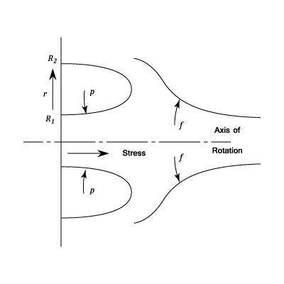
If\;\;\;R_1\rightarrow R_2 = R\;\;\;\;Then\;\;\;\;\hat{f}\rightarrow \frac{\rho \;\omega ^2\;R^2}{g}
(33)
23287/Rotating-Discs-and-Cylinders-4-0003.png

As in the case of a thin rotating cylinder. The variations in Stress are shown on the diagram.

Example 1 [imperial]
Problem

A thin uniform disc of 10 in. diameter with a central hole of 2 in. , runs at 10,000 r.p.m. Calculate the maximum Principal Stress and the maximum Shear Stress in the disc. Take \frac{1}{m}\;\;\;=\;\;0.3\; and Density = 0.28 lb.in.-3

Workings

The maximum Principal Stress will be at the inside and is given by equation (31)

\f[\hat{f}\;=\;\frac{0.28}{4\times 32.2\times 12}\left(\frac{10,000\times 2π }{60} \right)^2\;\left(0.7\times 1^2\;+\;3.3\times 5^2 \right)\f]

\f[=\;16,500\;lb.in^{-2}\f]

The maximum Shearing Stress at any radius is given by:

\f[\frac{1}{2}(f\;-\;p)\;=\;\left(\frac{ρ \;ω ^2}{8g} \right)\left[\left(3\;+\;\frac{1}{m} \right)\frac{R_1^2\;R_2^2}{r^2} \;+\;\left(1\;-\;\frac{1}{m} \right)r^2\right]\f]

It can be seen from the diagram that the greatest Stress difference occurs at \f[r\;=\;R_1\f] and the Maximum Shearing Stress is:

\f[\frac{0.28}{8\times 32.2\times 12}\left(\frac{10.000\times 2π }{60} \right)^2\left(3.3\times\frac{1^2\times5^2}{1^2}\;+\;0.7\times 1^2 \right)\;=\;8250\;lb.in.^{-2}\f]

Solution

The maximum Principal Stress = 16,500 lb.in-2

The maximum Shear Stress = 8250 lb.in.-2

Long Cylinders

Assume that the Longitudinal Stress is \displaystyle f_1 and that the Longitudinal Strain e is constant. i.e. the cross sections remain plane which must be true away from the ends. The analysis is similar that used for a rotating disc and the Strain Equations are:

E\,e = f_1 - \left(\frac{1}{m} \right)\left(f + p \right)
(34)
E\;\frac{du}{dr} = p - \left(\frac{1}{m}\right)\left(f + f_1
(35)
E\;\frac{u}{r} = f - \left(\frac{1}{m}\right)\left(p + f_1 \right)
(36)

Using Equations (40) and (41) eliminate \displaystyle \frac{du}{dr}

From Equation (41)

E\,.\,\frac{du}{dr} = f - \left(\frac{1}{m} \right)\left(p + f_1 \right) + \left[\frac{df}{dr} - \left(\frac{1}{m} \right)\left(\frac{dp}{dr} \right) - \left(\frac{1}{m}\right)\left(\frac{df_1}{dr}  \right) \right]
(37)

From Equation (40)

= p - \left(\frac{1}{m} \right)\left(f + f_1 \right)
(38)
\therefore\;\;\;\;\;\;(f - p)\left(1 + \frac{1}{m} \right) + r\times \frac{df}{dr}\;\;\left(\frac{r}{m} \right)\left(\frac{dp}{dr} \right) - \left(\frac{r}{m} \right)\left( \right) = 0
(39)

Substituting \displaystyle \frac{df_1}{dr} = \left(\frac{1}{m} \right)\left(\frac{df}{dr} + \frac{dp}{dr} \right) which was obtained from equation (39)

(f - p)\left(1 + \frac{1}{m} \right) + r\times \frac{df}{dr}\left(1 - \frac{1}{m^2} \right) - \left(\frac{r}{m} \right)\left(1 + \frac{1}{m}\right)\left(\frac{dp}{dr} \right) = 0
(40)
Or\;\;\;\;\;f - p - r\times \left(1 - \frac{1}{m} \right)\left(\frac{dp}{dr} \right) = 0
(41)

The equilibrium equation is as equation (8) and subtracting equation (46) we get.

- r\left(1 - \frac{1}{m} \right)\left(\frac{df}{dr} \right) - r\left(1 - \frac{1}{m} \right)\left(\frac{dp}{fdr} \right) = \frac{\rho \times r\times \omega ^2}{g}
(42)
Or\;\;\;\;\;\frac{df}{dr} + \frac{dp}{dr} = \frac{\rho \times r\times \omega ^2}{\left(1 - \frac{1}{m} \right)g}
(43)

Integrating:

Or\;\;\;\;\;f + p = \frac{\rho \times r^2\times \omega ^2}{2\left(1 - \frac{1}{m} \right)g} + 2A
(44)

This can be compared to equation (11) which is for a thin disc. It can be seen that the result for a long cylinder can be obtained from those for a thin disc by writing \displaystyle \frac{1}{1 - \frac{1}{m}}\;instead\;of\;1 + \frac{1}{m}

Solid Cylinder

The maximum Stress occcurs at the centre where p and f are equal

\hat{f} = \frac{3 - \frac{2}{m}}{1 - \frac{1}{m}}\times \frac{\rho \times\omega ^2\times R^2}{8g}
(45)
If\;\;\;\;\;\frac{1}{m} = 0.3
(46)
Then\;\;\;\;\;\hat{f} = \frac{2.4}{5.6}\times \frac{\rho \times\omega ^2\times R^2}{8g} = 0.43\;\frac{\rho \times \omega ^2\times R^2}{8g}
(47)

( This compares with \displaystyle 0.41\times\frac{\rho \times \omega ^2\times R^2}{8g} for a solid disc)

Hollow Cylinder

\displaystyle \hat{p} = \left(\frac{3 - \frac{2}{m}}{1 - \frac{1}{m}} \right)\times \frac{\rho \times \omega ^2}{8g}\times\left(R_2 - R_1 \right)^2

\displaystyle \hat{f} = \frac{\rho \times \omega ^2}{4g\left(1 - \frac{1}{m} \right)}\left[\left(1 - \frac{2}{m}\right)R_1^2 + \left(3 - \frac{2}{m} \right) R_2^2 \right]

These values do not differ greatly from those for a thin disc.

A Disc of Uniform Strength

Consider the condition of equal stress at all radii. i.e. \displaystyle p = f = Constant
23287/Rotating-Discs-and-Cylinders-5.png

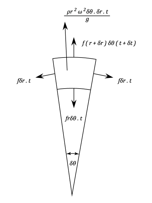
Le \displaystyle t be the thickness of the disc at a radius \displaystyle r and

assume that the thickness will be \displaystyle t + \delta t at radius \displaystyle r + \delta r

The mass of the element will be approximately

\rho \times r\times \delta \theta \times \delta r\times \frac{t}{g}
(48)

And the centrifugal Force will:

\rho \times r^2\times\omega ^2\times \delta \theta \times \delta r\times \frac{t}{g}
(49)

Hence the equilibrium Equation is:

2\;f\;\delta r\times \sin\frac{1}{2}\delta \theta  + f\;r\;\delta \theta \times t = f(r + \delta r)\;\delta \theta \;(t + \delta t) + \frac{\rho \;r^2\;\psi ^2\;t\;dr}{g}
(50)

Which in the limit is:

f\;t\times dr = f\;r\times dt + f\;t\times dr + \frac{\rho\;\omega^2\;t\times dr}{g}
(51)

Integrating:

\lnt\;= - \frac{\rho \;r^2\;\omega ^2}{2\;f\;g} + Constant
(52)
Or\;\;\;\;\;\;t = A\;e^{- \frac{p\;r^2\;\omega ^2}{2\;f\;g}}
(53)
Or\;\;\;\;\;\;t = t_0\;e^{- \frac{p\;r^2\;\omega ^2}{2\;f\;g}}
(54)
Example 1
Problem

A Turbine rotor Disc is 24 in. Diameter at the blade ring and is keyed to a 2 in diameter shaft. If the minimum thickness is 3/8 in. what should be the thickness at the shaft for a uniform stress of 30,000 lb./in\^2. aqt 10,000 r.p.m.? Density of material = 0.28 lb./in\^3.

Workings

\f[T\;=\;A\;e^{-\frac{ρ \,r^2\,ω ^2}{2f\;g}}\f]

\f[At\;\;\;\;\;\;\;r\;=\;12\;in.\f]

\f[t\;=\;\frac{3}{8}\;=\;A\;e^{-ρ \,ω ^2\times\frac{144}{2f\,g}}\f]

\f[At\;\;\;\;\;\;\;r\;=\;1\;in.\f]

\f[t\;=\;A\;e^{-\frac{ρ \,ω ^2}{2f\,g}}\;=\;\frac{3}{8}\;e^{ρ \,ω ^2\times \frac{143}{2f\,g}}\f]

\f[Where\;\;\;\;\;ρ \;ω ^2\times \frac{143}{2f\;g}\;=\;0.28\left(\frac{10,000π }{30} \right)^2\times \frac{143}{2}\times30,000\times 32.2\times 12\f]

\f[=\;1.89\f]

\f[\therefore\;\;\;\;\;\;t\;=\;\frac{3}{8}\;e^{1.89}\;\;=\;2.5\;inches\f]

Solution

The required thickness = 2.5 inches