
Rotating Discs and Cylinders
The Stresses and Strains generated in a rotating disc or cylinder.
You're viewing an older version of this page (#3924). View the current version.
Introduction
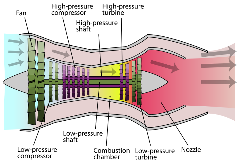
The rotation of a fast moving disc or cylindrical member can set up axial, circumferential and radial stresses. For instance, in the turbine section of an aircraft gas turbine engine, the rotor disc frequently turns at speeds in the region of 10000 r.p.m. This generates large amounts of stresses and strains on the material of the rotor disc. Similar loads are bourne by the cylindrical turbine rotor shafts that transmit the rotational movement from the turbine to the compressor section. To design a disc or shaft that can withstand these stresses without catastrophic failure in flight, it is important to understand the loads acting on them.
This section analyses the stress and strains acting on rotating discs and cylinders.
Discs of Uniform Thickness.
For a "thin" disc it can be assumed that the Stress in the Axial direction is zero. Due to the rotation of the disc, Circumferential (Hoop) and radial
Stresses will occur. Both these Stresses are Tensile. If the radial shift at a radius
is
, then the Strain Equations are:
Differentiating equation (2) and equating it to equation (1) gives:
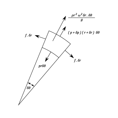
If the angular velocity of rotation is and the density of the disc material is
, then the element shown in the diagram is subjected to a centrifugal force:
Which for unit thickness:
The equilibrium equation in the radial direction is:
In the limit this equation reduces to:
From equation (8) obtain and substitute into equation (3)
Rearranging:
Integrating:
Subtracting equation (8)
Integrating:
Substituting from equation (11)
A Solid Disc
Since the Stresses can not be infinite at the centre of a solid Disc, B must be zero.
If R is the outside radius of the disc then rewriting equations (14) and (15):
From Which:
At the centre r = 0 and so:
This is the Maximum Stress.
At the outside :
For a value of
And at the outside:
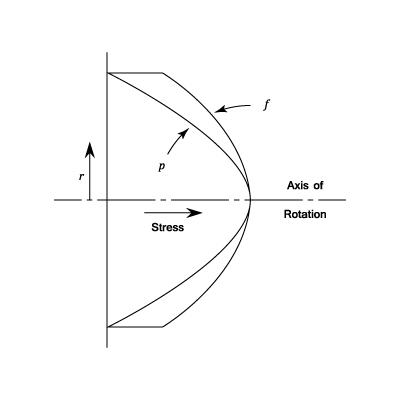
The variations of the Hoop and Radial Stresses with Radius are shown on the diagram.
A Disc with a Central Hole
The Radial Stress is Zero at both the inner and outer radii. If the value of these is , then using equation (14)
Solving the above two equations for A and B:
Substituting from equation(15)
p is a maximum when
Note that if is very small
which is tweiew the value which would be found in a solid disc.
At the outside
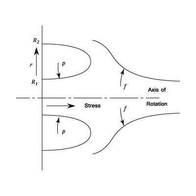
As in the case of a thin rotating cylinder. The variations in Stress are shown on the diagram.
Example 1 [imperial]
A thin uniform disc of 10 in. diameter with a central hole of 2 in. , runs at 10,000 r.p.m. Calculate the maximum Principal Stress and the maximum Shear Stress in the disc. Take and Density = 0.28 lb.in.-3
The maximum Principal Stress will be at the inside and is given by equation (31)
\f[\hat{f}\;=\;\frac{0.28}{4\times 32.2\times 12}\left(\frac{10,000\times 2π }{60} \right)^2\;\left(0.7\times 1^2\;+\;3.3\times 5^2 \right)\f]
\f[=\;16,500\;lb.in^{-2}\f]
The maximum Shearing Stress at any radius is given by:
\f[\frac{1}{2}(f\;-\;p)\;=\;\left(\frac{ρ \;ω ^2}{8g} \right)\left[\left(3\;+\;\frac{1}{m} \right)\frac{R_1^2\;R_2^2}{r^2} \;+\;\left(1\;-\;\frac{1}{m} \right)r^2\right]\f]
It can be seen from the diagram that the greatest Stress difference occurs at \f[r\;=\;R_1\f] and the Maximum Shearing Stress is:
\f[\frac{0.28}{8\times 32.2\times 12}\left(\frac{10.000\times 2π }{60} \right)^2\left(3.3\times\frac{1^2\times5^2}{1^2}\;+\;0.7\times 1^2 \right)\;=\;8250\;lb.in.^{-2}\f]
The maximum Principal Stress = 16,500 lb.in-2
The maximum Shear Stress = 8250 lb.in.-2
Long Cylinders
Assume that the Longitudinal Stress is and that the Longitudinal Strain e is constant, i.e., the cross sections remain plane which must be true away from the ends. The analysis is similar to that used for a rotating disc and the Strain Equations are:
Using Equations (40) and (41) eliminate
From Equation (41)
From Equation (40)
Substituting which was obtained from equation (39)
The equilibrium equation is as equation (8) and subtracting equation (46) we get.
Integrating:
This can be compared to equation (11) which is for a thin disc. It can be seen that the result for a long cylinder can be obtained from those for a thin disc by writing
Solid Cylinder
The maximum Stress occcurs at the centre where p and f are equal
(This compares with for a solid disc)
Hollow Cylinder
These values do not differ greatly from those for a thin disc.
A Disc of Uniform Strength
Consider the condition of equal stress at all radii, i.e. .
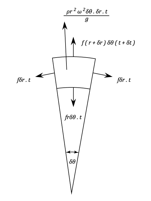
Le be the thickness of the disc at a radius
and
assume that the thickness will be at radius
The mass of the element will be approximately
And the centrifugal Force will be:
Hence the equilibrium Equation is:
Which in the limit is:
Integrating:
Example 1
A Turbine rotor Disc is 24 in. Diameter at the blade ring and is keyed to a 2 in diameter shaft. If the minimum thickness is 3/8 in. what should be the thickness at the shaft for a uniform stress of 30,000 lb./in\^2. aqt 10,000 r.p.m.? Density of material = 0.28 lb./in\^3.
\f[T\;=\;A\;e^{-\frac{ρ \,r^2\,ω ^2}{2f\;g}}\f]
\f[At\;\;\;\;\;\;\;r\;=\;12\;in.\f]
\f[t\;=\;\frac{3}{8}\;=\;A\;e^{-ρ \,ω ^2\times\frac{144}{2f\,g}}\f]
\f[At\;\;\;\;\;\;\;r\;=\;1\;in.\f]
\f[t\;=\;A\;e^{-\frac{ρ \,ω ^2}{2f\,g}}\;=\;\frac{3}{8}\;e^{ρ \,ω ^2\times \frac{143}{2f\,g}}\f]
\f[Where\;\;\;\;\;ρ \;ω ^2\times \frac{143}{2f\;g}\;=\;0.28\left(\frac{10,000π }{30} \right)^2\times \frac{143}{2}\times30,000\times 32.2\times 12\f]
\f[=\;1.89\f]
\f[\therefore\;\;\;\;\;\;t\;=\;\frac{3}{8}\;e^{1.89}\;\;=\;2.5\;inches\f]
The required thickness = 2.5 inches