
Stresses and Strains in loaded Circular Plates and Rings

You're viewing an older version of this page (#3537). View the current version.

View versions (5)

Circular Plates Symmetrically Loaded.

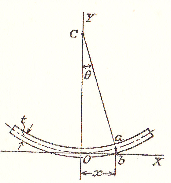
Consider a Diametral Section through a plate of thickness t. O is the centre of the plate and OX and OY are the principal axes in the plane of the diagram. The axis OZ is perpendicular to the screen.
13108/img_cir_1_0001.jpg

Let C be the Centre of Curvature of a section ab at a distance x from O . Then is the deflection y is small:-

\frac{dy}{dx}=\theta
(1)

The radius of curvature in the plane XOY is given by:

\frac{1}{R_{xx}}=\frac{d^2y}{dx^2}\;\;\;\;\;\;\;(Approximately)
(2)

Thus from equation (1)

\frac{1}{R_{xx}}=\frac{d\theta }{dx}
(3)

Note that, on a circle of radius x and centre O, lines such as ab form part of a cone with C as the apex. Hence C is the Centre of Curvature in the plane YOZ and:

\frac{1}{R_{yx}}\;=\;\frac{\theta }{x}\;\;\;\;\;\;\;\;(Approximately)
(4)

If u is the distance of any "fibre" from the neutral axis ( Which is assumed to be central) then proceeding as for "Pure Bending" in the planes XOY and YOZ the linear Strains are:

e_x=\frac{u}{R_{xy}} = \left(\frac{1}{E} \right)\left(f_x - \frac{f_z}{m} \right)
(5)

and

e_z=\frac{u}{R_{xy}} = \left(\frac{1}{E} \right)\left(f_z - \frac{f_x}{m} \right)
(6)

Where f_x and f_y are the Stresses in the directions OX and OZ. f_y is zero

Solving equations (#5) and (#6) for the Stresses and incorporating equations (#3) and (#4) gives:

f_x=\frac{E\;u}{1-\frac{1}{m^2}}\left(\frac{1}{R_{xy}}\;+\;\frac{1}{m\;R_{yz}} \right)=\frac{E\;u}{1 - \frac{1}{m^2}}\left(\frac{d\theta }{dx}\;+\;\frac{\theta }{m\;x} \right)
(7)
f_z = \frac{E\;u}{1 - \frac{1}{m^2}}\left(\frac{1}{m\;R_{xy}} + \frac{1}{R_{yz}} \right)\;=\;\frac{E\;u}{1\;-\;\frac{1}{m^2}}\left(\frac{1}{m}\times\frac{d\theta }{dx}\;+\;\frac{\theta }{x} \right)
(8)

The Bending Moment per unit length along OZ is \displaystyle M_{xy} which is given by:-

M_{xy}\times dz = \int_{-\frac{t}{2}}^{\frac{t}{2}}{f_x\times u\;dz\times du}
(9)
\therefore\;\;\;\;\;M_{xy}=D\left(\frac{d\theta }{dx} + \frac{\theta }{m\,x} \right)
(10)

By substitution from equation (#7)

D = \frac{E\;t^3}{12\left(1 - \frac{1}{m^2} \right)}
(11)

Similarly if M_{yz} is the Bending Moment per unit length about OX then

M_{yz}\times dx = \int_{-\frac{t}{2}}^{\frac{t}{2}}{f_z\times u\,dx\times du}
(12)

Using equation (#8)

M_{yz} = D\left[\left(\frac{1}{m} \right)\left(\frac{d\theta }{dx} \right) + \frac{\theta }{x} \right]
(13)

Note that:

f_x=M_{xy}\times \frac{12u}{t^3}
(14)
f_z=M_{yz}\times \frac{12u}{t^3}
(15)

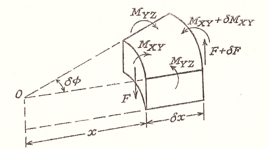
The diagram shows the Forces and Moments per unit length acting on an element which subtends an angle \delta \phi at the centre. F is the Shearing Force per unit length in the direction of OZ
13108/img_cir_1_0002.jpg

Now consider the equilibrium of the Couples in the Central Radial Plane.

i.e. \left(M_{xy}\;+\;\delta M_{xy} \right)\left(x\;+\;\delta x \right)\delta \phi - M_{xy}\times x\delta \phi - 2M_{yz}\times \delta x\times \sin\frac{1}{2}\delta \phi +f\;x\;\delta \phi \times \delta x\;=\;0
(16)

Which in the Limit reduces to:

M_{xy}\;+\;x\times \frac{\delta M_{xy}}{dx}\;-\;M_{yz}\;+\;Fx\;=\;0
(17)

substituting from Equations (#10) and (#13) gives:

\frac{d^2\theta }{dx^2} + \left(\frac{1}{x} \right)\left(\frac{d\theta }{dx} \right) - \frac{\theta }{x^2} = -\;\frac{F}{D}
(18)

This can be written as:

\left(\frac{d}{dx} \right)\left[\left(\frac{1}{x} \right)\times \frac{d(x\theta )}{dx} \right]\;=\;-\;\frac{F}{D}
(19)

If F is known as a function of x, this equation can be integrated to determine \theta and hence y. Bending Moments and Stresses can then be calculated.

Example 1

A particular cases will now be considered: A Plate Loaded with Uniformly distributed load of w per unit Area and a Concentrated load at Centre of P.

2\pi \,x\times F\;=\;\pi x^2\times w\;+\;P
(20)
\therefore\;\;\;\;\;\;\;F\;=\;\frac{w\,x}{2}\;+\;\frac{P}{2\pi \;x}
(21)

Per unit length of circumferentially (Except at x = 0)

Substituting in Equation (#19) and Integrating:-

\theta \;=\;-\;\frac{w\;x^3}{16\;D}\;-\;\left(\frac{P\;x}{8\pi \;D} \right)\left(2\ln x\;-\;1 \right)\;+\;\frac{C_1\,x}{2}\;+\;\frac{C_2}{x}
(22)

But From Equation (#1)

y=\int \theta \;dx + C_3
(23)
Blank
\therefore\;\;\;\;\;y\;=\;-\;\frac{w\;x^4}{64\;D}\;-\;\left(\frac{P\;x}{8\pi \;D} \right)\left(2\ln x\;-\;1 \right)\;+\;\frac{C_1\;x}{4}\;+\;C_2\;\ln x\;+\;C_3
(24)

Solid Circular Plate

Let the radius of the plate be R and the thickness t

Uniformly loaded, Edge freely supported

P=0 and since \theta and y can not be infinite at the centre then C_2=0 from Equation (#22) at x = 0, y = 0 and therefore C_3=0 from equation(24).

Using equations (10) and (22). At x=R, M_{xy}=0 therefore

-\frac{3\,w\,R^2}{16 D} + \frac{C_1}{2} - \frac{w\,R^2}{16 D\,m} + \frac{C_1}{2 m} = 0
(25)

Thus

C_1=\left(\frac{w\,R^2}{8\,D} \right)\left(\frac{3+\frac{1}{m}}{1+\frac{1}{m}} \right)
(26)
\text{Central Deflection} = y\;\;\;\;\;at\;\;\;\;\;x=R
(27)

Thus

y=\frac{w\;R^4}{64\,D} + \frac{w\,R^4}{32 D}\times \frac{3 + \frac{1}{m}}{1 + \frac{1}{m}} = \frac{w\;R^4}{64\;D}\left(\frac{5 + \frac{1}{m}}{1 + \frac{1}{m}} \right)
(28)

Eliminating D by substitution from Equation (#11)

=\left(\frac{3\,w\,R^4}{16\,E\,t^3} \right)\left(5 + \frac{1}{m} \right)\left(1 - \frac{1}{m} \right)
(29)

From Equation (#7)

f_x = \frac{E\;u}{!\;-\;\frac{1}{m^2}}\left(-\;\frac{w\,x^2}{16\,D}\times \left\{3 - \frac{1}{m} \right\} + \frac{w\;R^2}{16\,D}\left\{3 + \frac{1}{m} \right\} \right)
(30)

And at x=0

hat{f}=\frac{E\times \frac{t}{2}}{1 - \frac{1}{m^2}}\times \frac{w\;R^2}{16 D}\left(3 + \frac{1}{m} \right)
(31)
=\frac{3w\;R^2\left(3 + \frac{1}{m} \right)}{8 t^2}
(32)

From Equation (#8)

f_z\;=\;\frac{E\;u}{1\;-\;\frac{1}{m^2}}\left(-\;\frac{w\,x^2}{16\;D}\left\{\frac{3}{m}\;+\;1 \right\} \;+\;\frac{w\;R^2}{16\;D}\left\{3\;+\;\frac{1}{m} \right\}\right)
(33)

As above when x=0, f_z=\hat{f_z}. Therefore \hat{f_x}=\hat{f_z}

Note: the Maximum Stresses occur at the centre.

Uniformly Loaded with the Edge Clamped

As in the last case P=0 and C_2=0 at x=0, y=0. Therefore C_3=0 from equation(#24) At x=R,

\frac{dy}{dx}=\theta =0
(34)

i.e. from Equation (#22)

-\frac{w\;R^3}{16\;D} + C_1\times \frac{R}{2}\;=\;0
(35)
\therefore\;\;\;\;\;\;C_1 = \frac{w\;r^2}{8\;D}
(36)

Using Equation (#24):

\text{Central Deflection}=-\frac{w\;r^4}{64\;D} + \frac{w\;R^4}{32\;D} = \frac{w\;R^4}{64\;D}
(37)

Eliminating D by using equation (11)

=\left(\frac{3\,w\;R^4}{16\;E\;t^3} \right)\left(1 - \frac{1}{m^2} \right)
(38)

from Equation (#7)

f_x\;=\;\left(\frac{E\;u}{1\;-\;\frac{1}{m^2}} \right)\left(-\;\frac{w\;x^2}{16\;D}\left\{3\;+\;\frac{1}{m} \right\}\;+\;\frac{w\;R^2}{16\;D}\left\{1\;+\;\frac{1}{m} \right\} \right)
(39)

This Stress has its greatest numerical value when x = R ( i.e. at the clamped edge), thus

\hat{f_x}=\frac{E\times \frac{t}{2}}{1 - \frac{1}{m^2}}\times \frac{w\;R^2}{16\;D}\times 2
(40)
=\frac{3\;w\;R^2}{4\;t^2}
(41)

From Equation (#8)

f_z=\frac{E\;u}{1 - \frac{1}{m^2}}\left(\frac{-\;w\;x^2}{16\,D}\left\{\frac{3}{m}\;+\;1 \right\}\;+\;\frac{w\;R^2}{16\;D} \left\{1+\frac{1}{m} \right\}\right)
(42)

From which

\hat{f_z}\;=\;\frac{E\times\frac{t}{2}}{1\;-\;\frac{1}{m^2}}\times \frac{w\;R^2}{16\;D}\times \left(1\;+\;\frac{1}{m} \right)
(43)
=\;\frac{3\;w\;R^2(1\;+\;\frac{1}{m})}{8\;t^2}\;\;\;\;\;\;\;(At\;the\;Centre)
(44)

Central Load P, Edge Freely Supported (w=0)

At x=0, \theta=0 therefore from equation(#22) C_2=0 and y=0. From equation(#24) C_3=0

Note: (L\times t\times (x\;\ln x)=0)

At x=R, M_{xy}=0 do from equation(#10)

-\left(\frac{P}{8\;\pi \;D } \right)\left(2\;\ln\,R - 1 \right)\;\left(\frac{P\;R}{8\pi D} \right)\left(\frac{2}{R} \right) + \frac{C_1}{2}\;-\;\left(\frac{P}{8\pi \;D\;m} \right)\left(2\;\ln R - 1 \right)\;+\;\frac{C_1}{2\,m} = 0
(45)

From which

c_1 = \frac{P}{4\pi \,D}\left(2\,\ln R + \frac{1 - \frac{1}{m}}{1 + \frac{1}{m}} \right)
(46)

Thus

\text{Central deflection} = \frac{P\,R^2}{8\pi \,D}\left(\ln R - 1 \right) + \frac{P\;R^2}{16\pi \,D}\left(2\,\ln R + \frac{1\;-\;\frac{1}{m}}{1 + \frac{1}{m}} \right)
(47)
=\frac{P\;R^2}{16\pi \,D}\times \frac{(3 + \frac{1}{m})}{(1\;+\;\frac{1}{m})}
(48)
=\frac{3P\;R^2}{4\pi\;E\;t^3}\times \left( 3 +\frac{1}{m} \right)\left(1\;-\;\frac{1}{m} \right)
(49)

From Equation (#7)

f_x = \frac{E\;u}{1\;-\;\frac{1}{m^2}}\times \frac{P}{4\pi \,D}\left(1\;+\;\frac{1}{m} \right)\ln\frac{R}{x}
(50)
=\left(\frac{3P}{2\pi \,t^2} \right)\left(1 + \frac{1}{m} \right)\ln\frac{R}{x}
(51)

Note u=\frac{t}{2}

And from equation (#8)

f_z =\left(\frac{3P}{2\pi \,t^2} \right)\left[\left(1\;+\;\frac{1}{m} \right)\ln\frac{R}{x}\;+\;1\;-\;\frac{1}{m} \right]
(52)

These Stresses appear to become infinite at the centre but it must be realised that the load can not be applied at a point but must extend over a finite area. If this area can be estimated then the maximum Stresses can be obtained.

Loaded round a circle, Edge freely supported

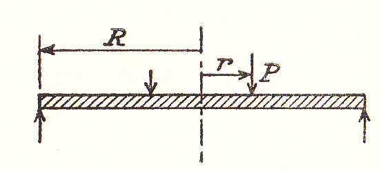
Let a total load P be distributed around a circle of radius r:
13108/img_0001_1.jpg

It is necessary to divide the plate into two regions, one for x < r and the other for x > r. At x = r the values of \theta, y and M_{xy} must be the same for both regions.

If x<r, w=0 and P=0

Hence from Equation (#22)

\theta = \frac{C_1 x}{2} + \frac{C_2}{x}
(53)

And from Equation (#24)

y=\frac{C_1 x^2}{4} + C_2\;\ln x + C_3
(54)

Since \theta and y are not infinite at x=0 then C_2=0 and since y=0 when x=0 and C_3=0 then above equations reduce to:

\theta =\frac{C_1 x}{2}
(55)

And

y=\frac{C_1\;x^2}{4}
(56)

If x>r and w=0 From Equation (#22)

\theta =-\left(\frac{P x}{8\pi D} \right )\left(2 \ln x-1 \right) + \frac{C_1'x}{2} + \frac{C_2'}{x}
(57)

And from Equation (#24)

y=-\left(\frac{P\;x^2}{8\pi \;D} \right)\left(\ln x\;-\;1 \right)\;+\;\frac{C_1'x^2}{2}\;+\;C_2'\;\ln {x}\;+\;C_3'
(58)

Equating the values of \theta and M_{xy} at x=r gives the following equations:

-\left(\frac{P\,r}{8\pi \;D} \right)\left(2\;\lnr\;-\;1 \right) + \frac{C_1'\;r}{2} + \frac{C_2'}{r} = \frac{C_1\;r}{2}
(59)
-\left(\frac{P\,r^2}{8\pi \;D} \right)\left(\ln r\;-\;1 \right) + \frac{C_1'\;r^2}{4} + C_2'\;\ln r = \frac{C_1\;r^2}{4}
(60)

And

\left(\frac{P}{8\pi \;D} \right)\left[\left(1\;+\;\frac{1}{m} \right)2\;\ln r + 1 -\frac{1}{m} \right]\:+\;\left(\frac{C_1'}{2} \right)\left(1 + \frac{1}{m} \right) - \left(\frac{C_2'}{r^2} \right)\left(1 - \frac{1}{m} \right)
(61)
=\left(\frac{C_1}{2} \right)\left(1\;+\;\frac{1}{m} \right)
(62)

M_{xy}=0 at x=R gives:

\left(\frac{P}{8\pi D} \right)\left[\left(1 + \frac{1}{m} \right)2\;\ln R + 1 - \frac{1}{m} \right] + \left(\frac{C_1'}{2} \right)\left(1 + \frac{1}{m} \right) - \left(\frac{C_2'}{R^2} \right)\left(1 - \frac{1}{m} \right) =0
(63)

From Equations (#64) to (#70) the constants are found to be:

C_1'=\frac{P}{4\pi \;D}\left[2\;\lnR\;+\;\frac{R^2\;-\;r^2}{R^2}\left(\frac{1\;-\;\frac{1}{m}}{1\;+\;\frac{1}{m}} \right) \right]
(64)
C_2'=-\frac{P\;r^2}{8\pi \;D}
(65)
C_3'=\frac{P\;r^2}{8\pi \;D}\left(\ln r\;-\;1 \right)
(66)

The Central Deflection is given by the value of y at x = R and by substitution equation (24) reduces to:-

y=\left(\frac{P}{8\pi \;D} \right)\left[\left(R^2 - r^2 \right)\times  \frac{\left(3 + \frac{1}{m} \right)}{2\left(1 + \frac{1}{m} \right)} -r^2\;\ln\frac{R}{r} \right]
(67)

For x>r

M_{xy} = \left(\frac{P}{8\pi \right)\left[\left(1 + \frac{1}{m} \right)2\;\ln x + \left(1 + \frac{1}{m} \right)\times r^2\left(\frac{1}{x^2}\;-\;\frac{1}{R^2} \right)\right]}
(68)

Which has a maximum value at x = r

Hence from equation (#14)

\hat{f}=\left(\frac{6}{t^2} \right)\;M_{xy}
(69)
=\left(\frac{3\;P}{4\pi \;t^2} \right)\left[\left(1\;+\;\frac{1}{m} \right)2\;\ln\frac{R}{r}\;+\;\left(1\;-\;\frac{1}{m} \right)\left(\frac{R^2\;-r^2}{R^2} \right) \right]
(70)

Similarly:

M_{yz}=\left(\frac{P}{8 \pi } \right)\left\{ \left(1 + \frac{1}{m} \right)2 \ln\frac{R}{x} + \left(1 - \frac{1}{m} \right)\left[\frac{2R^2 -r^2}{R^2} - \frac{r^2}{x^2}\right]  \right\}
(71)
\hat{f_z}=\left(\frac{3 P}{4\pi \;t^2} \right)\left[\left(1 + \frac{1}{m} \right)2 \ln\frac{R}{r} + \left(1 - \frac{1}{m} \right)\left(\frac{R^2 -r^2}{R^2} \right) \right]=f_x
(72)

Annular Ring , Loaded around the Inner edge
13108/img_cir_1_0004.jpg

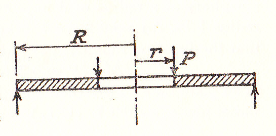
The ring is loaded with a total load P around the inner edge and is freely supported around the outer edge. M_{xy}=0 at x=R and at x=r.

-\left(\frac{P}{8\pi D} \right)\left[\left(1 + \frac{1}{m} \right)2\;\ln R + 1 - \frac{1}{m} \right] + \left(\frac{C_1}{2} \right)\left(1 + \frac{1}{m} \right) - \left(\frac{C_2}{R^2} \right)\left(1 - \frac{1}{m} \right) = 0
(73)

And

-\;\left(\frac{P}{8\pi D} \right)\left[\left(1 + \frac{1}{m} \right)2 \ln r + 1 - \frac{1}{m} \right] + \left(\frac{C_1}{2} \right)\left(1 + \frac{1}{m} \right) - \left(\frac{C_2}{r^2} \right)\left(1 - \frac{1}{m} \right) = 0
(74)

Subtracting and solving:

C_2=\frac{P}{4\pi D}\times \frac{1 + \frac{1}{m}}{1 - \frac{1}{m}}\times \frac{R^2 r^2}{R^2 - r^2}\times \ln \frac{R}{r}
(75)

And then

C_1=\frac{P}{4\pi D}\left[\frac{2(R^2 \ln R - r^2 \ln r)}{R^2 - r^2} + \frac{1 -\frac{1}{m}}{1 + \frac{1}{m}} \right]
(76)

Then,

\frac{M_{xy}}{D} = -\left(\frac{P}{8\pi D} \right)\left[\left(1\;+\;\frac{1}{m} \right)2 \ln x + 1-\frac{1}{m} \right] + \left(\frac{C_1}{2} \right)\left(1\;+\;\frac{1}{m} \right) - \left(\frac{C_2}{x^2} \right)\left(1\;+\;\frac{1}{m} \right)
(77)
\frac{M_{yz}}{D}\;=\;-\;\left(\frac{P}{8\pi D} \right)\left[\left(1\;+\;\frac{1}{m} \right)2\;\ln x - \left(1 +\frac{1}{m} \right) \right]\;+\;\left(\frac{C_1}{2} \right)\left(1 + \frac{1}{m} \right)\;-\;\left(\frac{C_2}{x^2} \right)\left(1 + \frac{1}{m} \right)
(78)

The maximum Bending Moment is M_{yz} at x=r, therefore

\hat{f_z}=\left(\frac{6}{t^2} \right)\;M_{yz}
(79)
=\frac{3\;P}{\pi \;t^2}\times \frac{\left(1\;+\;\frac{1}{m} \right)}{R^2\;-\;r^2}\times \ln\frac{R}{r}
(80)