
Circular Plates
Bending moment is the algebraic sum of all moments located between a cross section and one end of a structural member; a bending moment that bends the beam convex downward is positive, and one that bends it convex upward is negative.
A shear stress is defined as the component of stress coplanar with a material cross section. Shear stress arises from a force vector perpendicular to the surface normal vector of the cross section.
Deflection is a term that is used to describe the degree to which a structural element is displaced under a load.
Structural loads or actions are forces, deformations or accelerations applied to a structure or its components.Loads cause stresses, deformations and displacements in structures.
Stresses and Strains in loaded Circular Plates and Rings
You're viewing an older version of this page (#3877). View the current version.
Circular Plates Symmetrically Loaded.
Consider a Diametral Section through a plate of thickness .
is the centre of the plate and
and
are the principal axes in the plane of the diagram. The axis
is perpendicular to the screen.
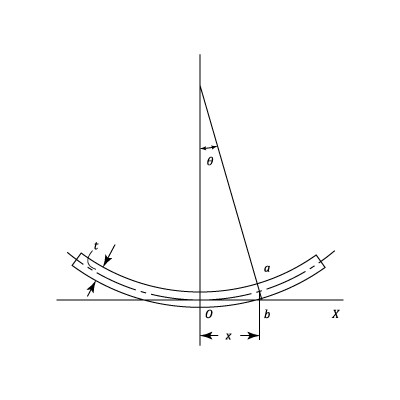
Let be the Centre of Curvature of a section
at a distance
from
. Then if the deflection
is small:
The radius of curvature in the plane is given by:
(Approximately)
Thus from equation (#1)
Note that, on a circle of radius and centre
, lines such as
form part of a cone with
as the apex. Hence
is the Centre of Curvature in the plane
and:
(Approximately)
If is the distance of any "fibre" from the neutral axis (Which is assumed to be central) then proceeding as for "Pure Bending" in the planes
and
the linear Strains are:
And
Where and
are the Stresses in the directions
and
.
is zero
Solving equations (#4) and (#5) for the Stresses and incorporating equations (#2) and (#3) gives:
The Bending Moment per unit length along is
which is given by:
By substitution from equation (#6)
Similarly if is the Bending Moment per unit length about
then
Using equation (#7)
Note that:
The diagram shows the Forces and Moments per unit length acting on an element which subtends an angle at the centre.
is the Shearing Force per unit length in the direction of
.
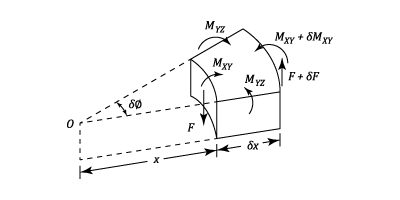
Now consider the equilibrium of the Couples in the Central Radial Plane.
i.e.
Which in the Limit reduces to: Substituting from Equations (#8) and (#10) gives:
This can be written as:
If is known as a function of
, this equation can be integrated to determine
and hence
. Bending Moments and Stresses can then be calculated.
Particular case
A Plate Loaded with Uniformly distributed load of per unit Area and a Concentrated load at Centre of
.
Per unit length of circumferentially (Except at )
Substituting in Equation (#12) and Integrating:
But From Equation (#1)
Example 1
A Plate Loaded with Uniformly distributed load of w per unit Area and a Concentrated load at Center of P.
\f[2π \,x\times F\;=\;π x^2\times w\;+\;P\f] \f[\therefore\;\;\;\;\;\;\;F\;=\;\frac{w\,x}{2}\;+\;\frac{P}{2π \;x}\f]
Per unit length of circumferentially (Except at x = 0)
Substituting in Equation (#19) and Integrating:
\f[θ \;=\;-\;\frac{w\;x^3}{16\;D}\;-\;\left(\frac{P\;x}{8π \;D} \right)\left(2\ln x\;-\;1 \right)\;+\;\frac{C_1\,x}{2}\;+\;\frac{C_2}{x}\f]#22 But From Equation (#1) \f[y=\int θ \;dx + C_3\f]#23
\f[\therefore\;\;\;\;\;y\;=\;-\;\frac{w\;x^4}{64\;D}\;-\;\left(\frac{P\;x}{8π \;D} \right)\left(2\ln x\;-\;1 \right)\;+\;\frac{C_1\;x}{4}\;+\;C_2\;\ln x\;+\;C_3\f]#24
Solid Circular Plate
Let the radius of the plate be and the thickness
.
Uniformly loaded, Edge freely supported
and since
and
can not be infinite at the centre then
from Equation (#13) at
,
and therefore
from equation (#14).
Using equations (#8) and (#13). At ,
therefore
Thus,
Central Deflection =
at
Thus,
Eliminating by substitution from Equation (#9)
From Equation (#6)
And at
From Equation (#7)
As above when ,
. Therefore
Note: the Maximum Stresses occur at the centre.
Uniformly Loaded with the Edge Clamped
As in the last case and
at
,
. Therefore
from equation(#14)
At ,
i.e. from Equation (#13),
Using Equation (#14),Central Deflection =
Eliminating by using equation (#9)
From Equation (#6)
This Stress has its greatest numerical value when ( i.e. at the clamped edge), thus
From Equation (#7)
From which,
(At the Centre)
Central Load P, Edge Freely Supported (w=0)
At ,
therefore from equation (#13)
and
. From equation(#14)
Note:
At ,
do from equation (#8)
From which,
Thus, Central deflection
From Equation (#6)
Note:
And from equation (#7),
These Stresses appear to become infinite at the centre but it must be realised that the load can not be applied at a point but must extend over a finite area. If this area can be estimated then the maximum Stresses can be obtained.
Loaded round a circle, Edge freely supported
Let a total load be distributed around a circle of radius
:
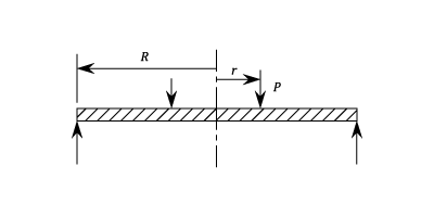
It is necessary to divide the plate into two regions, one for and the other for
. At
the values of
,
and
must be the same for both regions.
- If
,
and
Hence, from Equation (#13) And from Equation (#14),
Since and
are not infinite at
then
and since
when
and
then above equations reduce to:
And,
- If
and
From Equation (#13),
And from Equation (#14),
Equating the values of and
at
gives the following equations:
And
at
gives:
From Equations (#15) to (#16) the constants are found to be:
The Central Deflection is given by the value of at
and by substitution equation (#14) reduces to:
- For
Which has a maximum value at
Hence from equation (#11)
Similarly:
Annular Ring , Loaded around the Inner edge
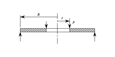
The ring is loaded with a total load around the inner edge and is freely supported around the outer edge.
at
and at
.
And,
Subtracting and solving: And then
Then,
The maximum Bending Moment is at
, therefore