Velocity and Acceleration
The analysis of velocity and acceleration in a range of mechanisms including Klein's Construction for piston acceleration
You're viewing an older version of this page (#3541). View the current version.
Introduction
The Theory of Machines is concerned with the Motion of parts of machines and the forces which act on those parts. In most cases these forces are not constant and their calculation demands that we know the velocities and accelerations which occur in the various components.
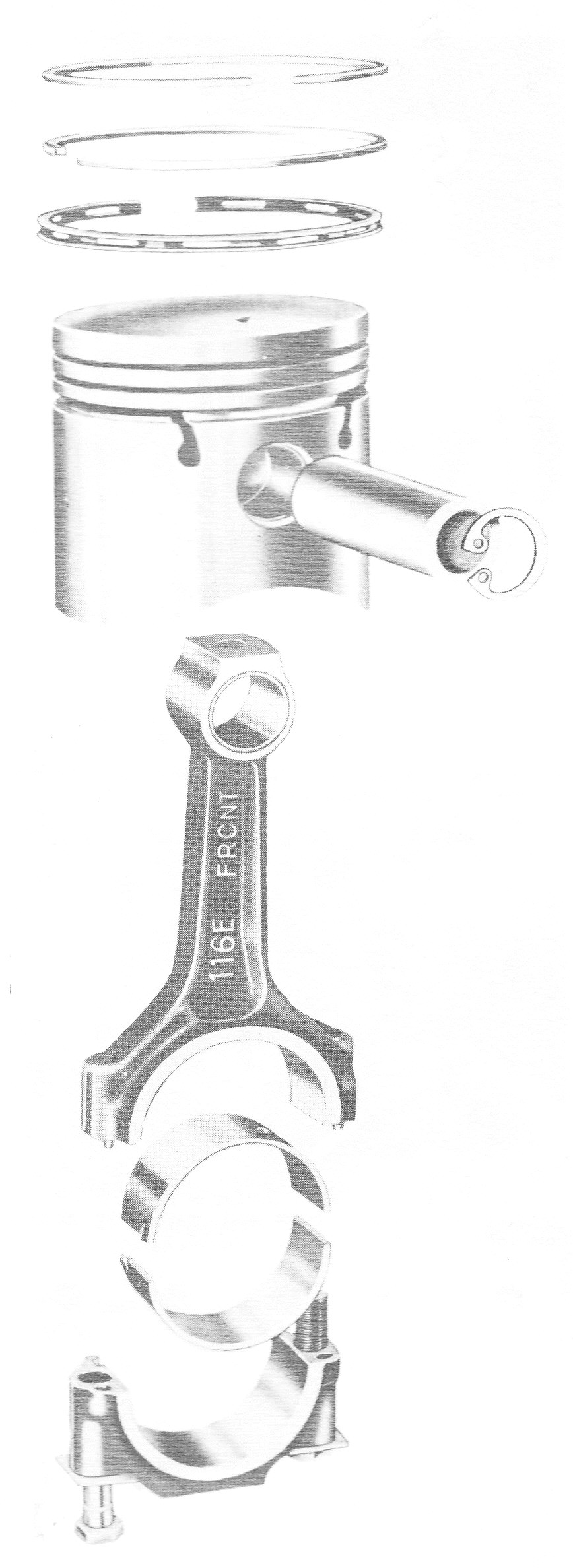
The concept of Instantaneous Centres of Velocity was covered in the section on Mechanisms. In this section the Analysis of Velocity and Acceleration are considered with particular reference to Cranks and Pistons. Klien's Construction for Piston Acceleration is introduced and a description of the Coriolis Component is given.
Analysis of Velocity and Accelerations Components.
a) Velocity
In the diagram the point P moves in the Plane XOY. The length OP = r and the . Then:-
And
Differentiating with respect to time :-
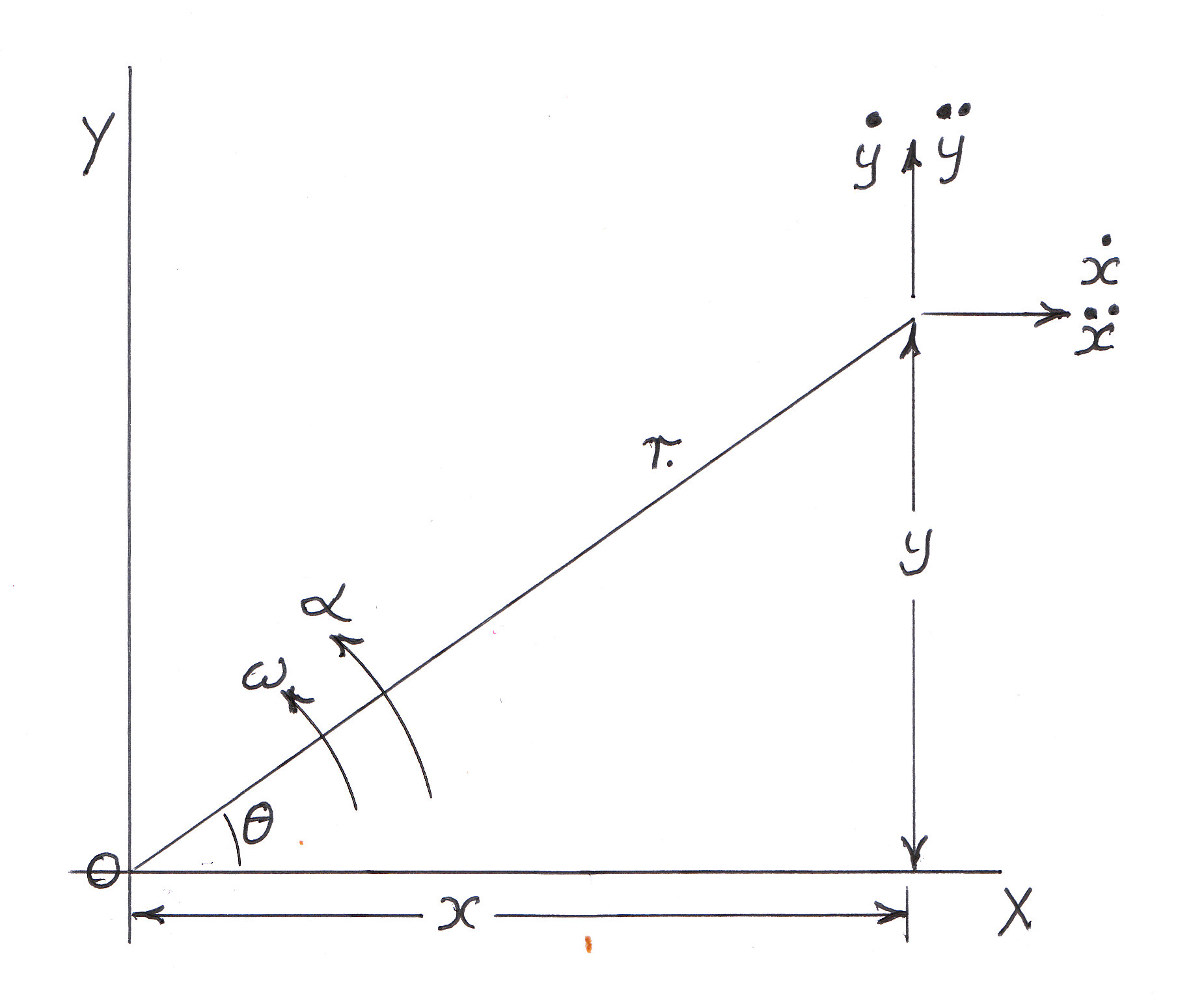
The radial component of Velocity v ( i.e. in the direction of OP) is given by:-
And using equations (3) and (4)
Which is the rate of increase of OP
The tangential component of velocity (i.e.Perpendicular to OP in the direction of increasing)
Where
b) Acceleration
Differentiating (3) and (4)
The Radial components of acceleration
And from equation (5)
The Tangential component of acceleration
By substitution:-
(Note )
Of these four terms in equations (11) and (13)
is the rate of change of radial velocity
is the centripetal acceleration due to the rotation of OP
is due to the change in angular velocity.
is called the compound supplementary acceleration or Coriolis Component Notice that the direction of this is the same as
when v is radially outwards.
The Velocity and Acceleration of a Piston by Analysis
In the following analysis is the uniform angular velocity of the crank. The positive direction of velocity and acceleration is away from the crankshaft.

And
From the above three equations:-
Instantaneous Centre Method for Velocities.
This has been covered in the section on Mechanisms.
The Vector Method for Velocity and Acceleration.
The Law of addition of velocities states that:-
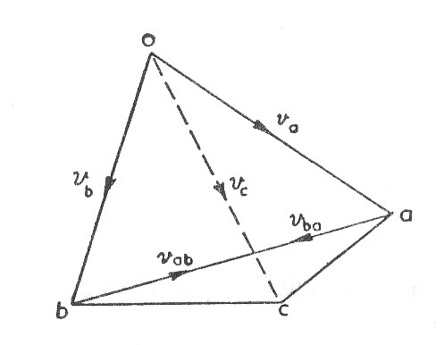
"Absolute velocities (or accelerations) are given from O to the corresponding point on the diagram.
For Velocities
- The relative velocity between two points A and B on the same link of a mechanism must be perpendicular to the line joining the points and is equal to
(Equation (4))since r is constant and
is zero.
- The relative velocity for two points sliding over one another is along the common tangents of their paths and represents the component
for Acceleration
The relationships for acceleration are similar to those given for velocity:-
- Acceleration of B = Acceleration of A + Acceleration of B relative to A
- Equations (11) and (13) are the general expressions for the radial and tangential components of relative acceleration.
- For two points on the same link
leaving centripetal component
(which can be calculated when the velocities are determined) and the tangential component
- For a uniformly rotating Crank
leaving the centripetal as the only term.
- The Coriolis component arises when a point on one link is sliding along another link wwhich is itself rotating.
If A,B,C, are three points on the same link of a mechanism and a,b,c, are the corresponding points on the velocity (or acceleration) diagram, it can be shown that the triangles ABC and abc are similar. abc is called the Velocity (or acceleration) image of the link.
Klein's Construction for Piston Acceleration.
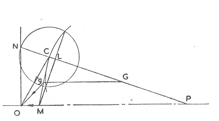
The above is a diagramatic sketch of a piston; connecting rod; crank assembly where:-
- PC is the connecting rod with C the Crank Pin.
- OC is the crank.
- OP is the line of stroke.
- P is the gudgeon pin
The Construction is as follows:-
- Extend PC to meet the line through O perpendicular to the line of stroke. Let the point of intersection be N.
- Draw a circle centre C and radius CN.
- Draw a circle with CP as diameter.
- Let the common cord cut the line CP at L and the line of stroke PO at M.
Then the quadrilateral OCLM represents, to a certain scale, the acceleration diagram for OCP. It can be shown that this scale is .
- The Cewntripetal acceleration of the crank pin is
- The piston acceleration is
- CL is the Centripetal component and LM the Tangential component of the acceleration of P relative to C, so that CM is the acceleration image of CP.
- For any point Q on CP draw a line parallel to OP cutting CM in q. The acceleration of
in magnitude and direction.
Worked Examples
The workings associated with the following Examples have been "Hidden". Th view them pease click om the red buttons.
Example 1
An aeroplane A flying at 180 m.p.h. in a direction North of West sights another B due North of A. After 30 seconds flying B is seen to be in a North-Easterly direction from A and after a further 45 seconds B is directly astern of A. If B is flying at a constant speed in a direction due South, find:- (a) The speed of B (b)For how long B is within 2 miles of A (U.L.)

Example 2
The quick return mechanism for a shaping machine is shown in the diagram. The upper end of the slotted lever is pin jointed to the ram and tool box at at D so that this point moves in a horizontal straight line whilst the lower end slides over a block at C mounted on trunnion bearings.
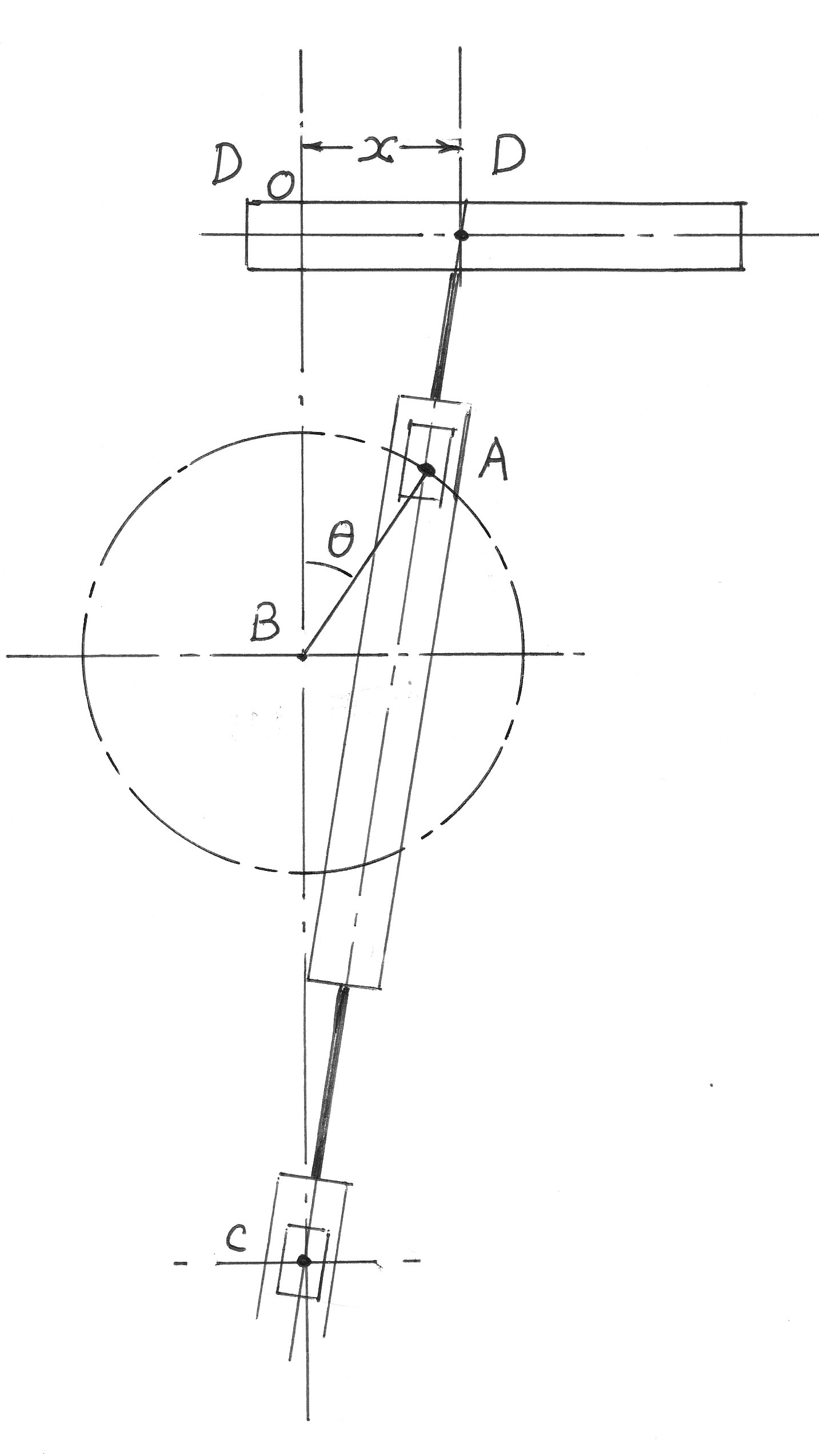
It is driven by the crank BA which turns at uniform angular velocity about the fixed centre B, through the slide block at A. If the ratio of the lengths BA/BC is denoted by k and
is the angle BA has turned from the upwards vertical, show from the geometry that the displacement of the tool box from its mid point is :-
And determine the corresponding velocity and acceleration.
Example 3
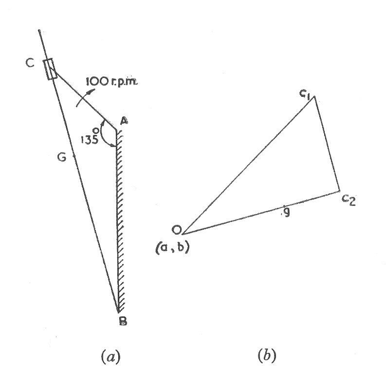
In the mechanism shown in the diagram, the crank AC is 5 in. long and rotates clockwise about a centre A with a speed of 100 r.p.m.. The slotted lever BC rotates about a fixed centre B, 10 in. vertically below A. Its centre of gravity G is 9 in. from B, its weight 25 lb. and its radius of gyration about G is 8 in. For the position shown in which the angle BAC is
determine graphically the angular velocity of BC, the linear velocity of G, the velocity of the sliding block in slot, the angular velocity of the pin at C relative to the block. Also calculate the kinetic energy stored in the lever BC.
Example 4
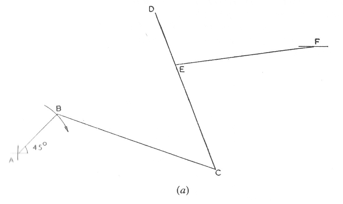
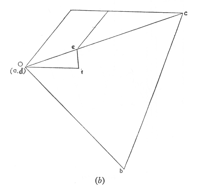
In the linkwork shown in the following Diagram, the crank AB rotates about A at a uniform speed of 120 r.p.m. The lever DC oscillates about the fixed point D being connected to AB by the coupler BC. The block F moves in horizontal guides and is driven by the link EF.
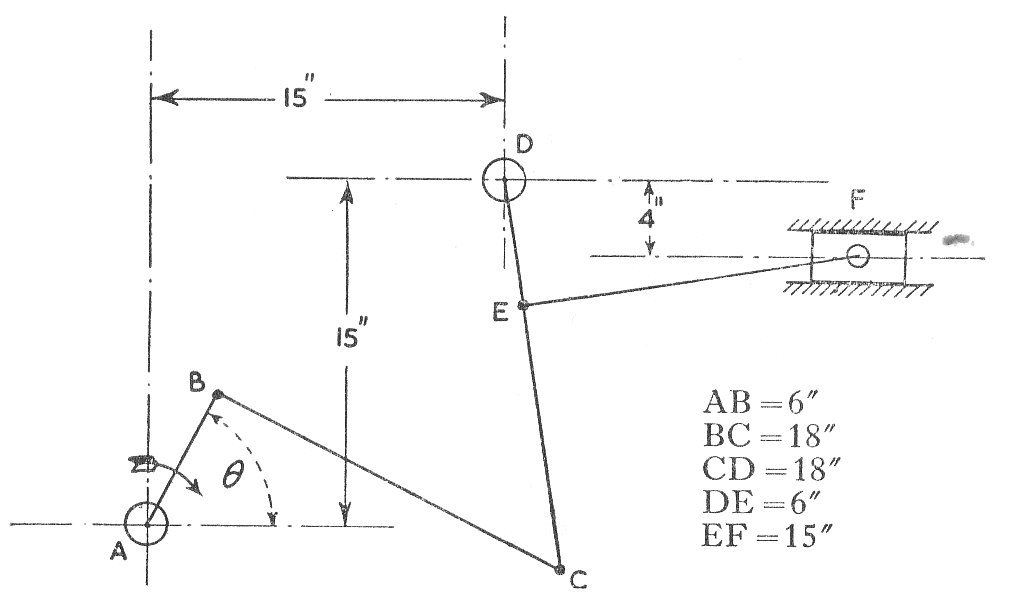
When the angle determine (a) the velocity of F (b) the angular velocity of DC and (c) the rubbing speed at the pin C which is 2 in. diameter. (U.L.)
Example 5
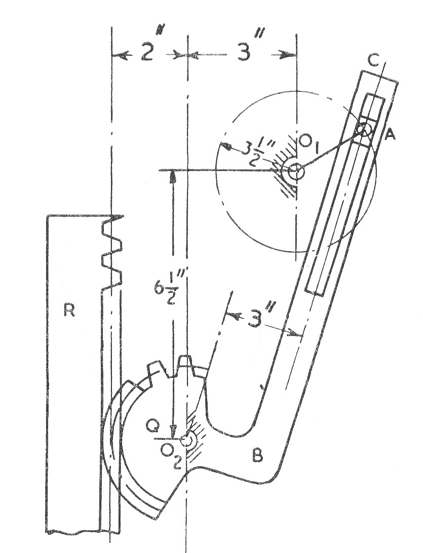
In the mechanism shown in the diagram, the crank rotates at a constant speed of 60 r.p.m., in a clockwise direction, imparting a vertical reciprocating motion to the rack R, by means of the toothed quadrant Q.
are fixed centres and the slotted bar BC and the quadrant Q rock on
.
Determine (aq) the linear speed of the rack when the angle (b)The ratio of the times of lowering and raising the rack and (c) The length of the stroke of the rack. (U.L.)
Example 6
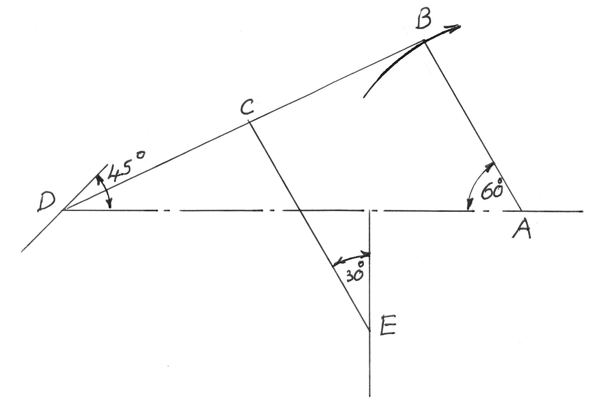
The diagram shows a mechanism in which the crank AB turns uniformly at 180 r.p.m., the blocks at D and E working in frictionless guides. AB = 1.5 ft.; BD = 5 ft. ; BC = 3 ft. ; CE = 3 ft.
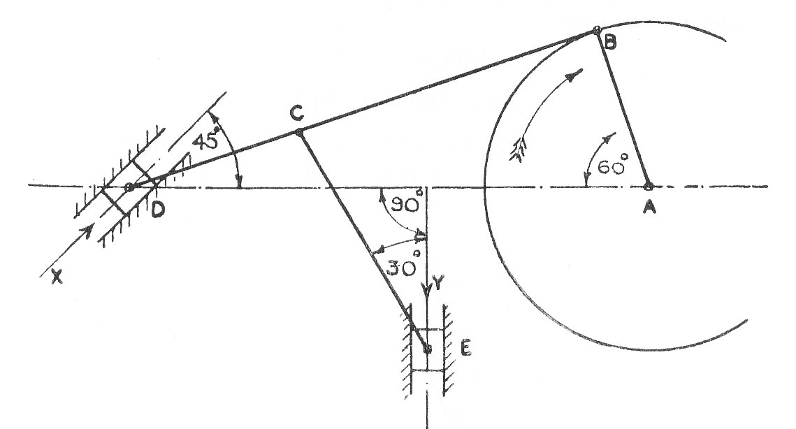
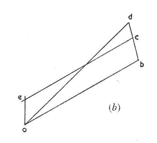
Draw the velocity vector diagram and state the velocities of the blocks D and E in their guides.
Find the turning Moment at A if a force of 100 lb. acts on D in the direction of the arrow X and a force of 150 lb. acts on E in the direction of arrow Y (U.L.)
Example 7
For the engine shown in the Diagram, the crank radius CB is 2.25 in. and the length of the connecting rod Ab is 9.25 in. between centres.
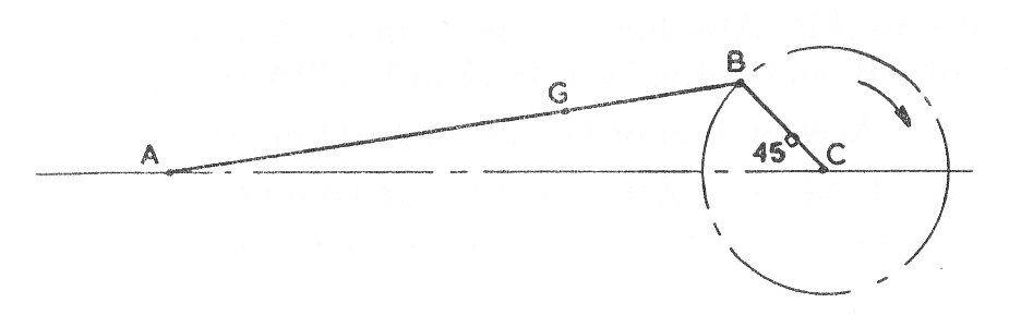
The centre of gravity of the rod is at G which is 3 in. from B. The engine speed is 1200 r.p.m. For the position shown, in which CB is turned from CA, find graphically the velocity of G and the angular acceleration of AB. Indicate the direction of each of these values.
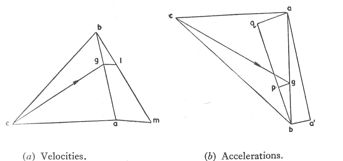
Example 8
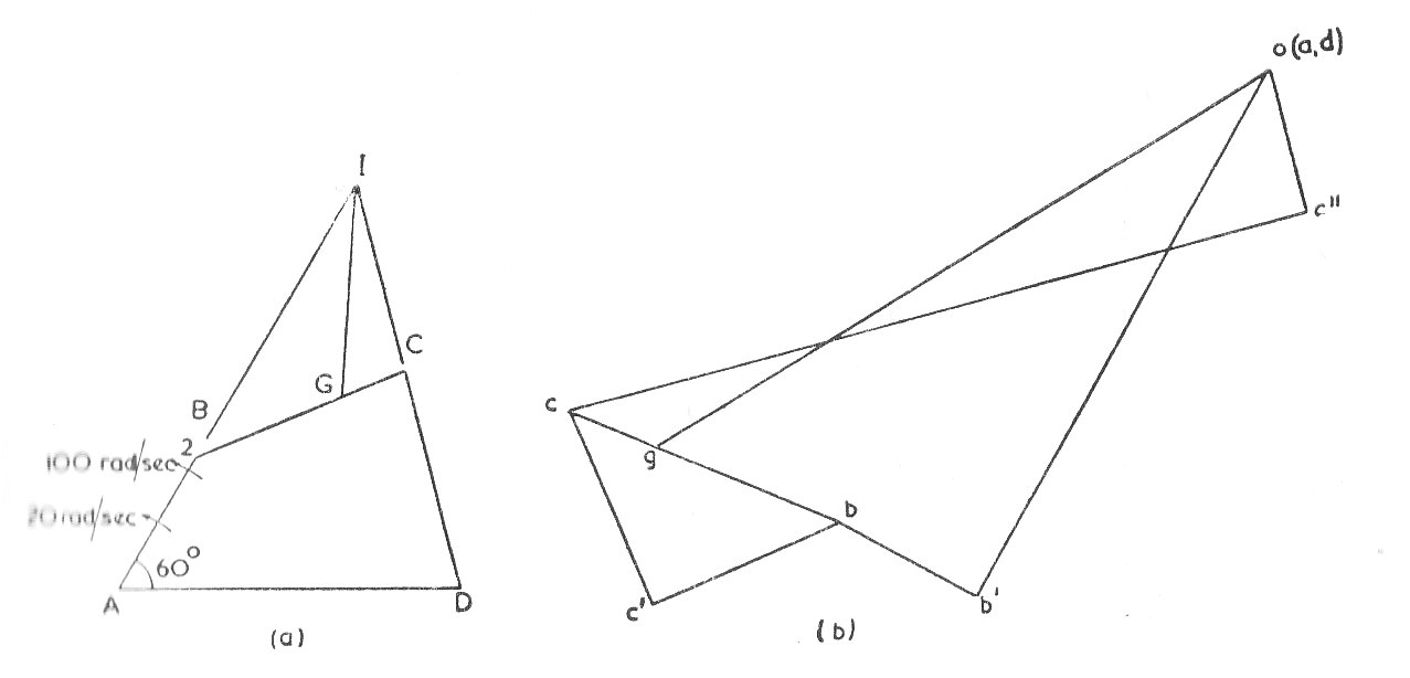
In a four bar chain ABCD, A and D are fixed centres 2.5 in. apart on a horizontal line. The driving crank AB = 1 in., the driven crank DC = 1.5 in. and the coupler BC = 1.5 in. with its centre of gravity G at 0.5 in. from C. When AB is turned through anti-clockwise from AD, B and C are on the same side as AD. If, for this position, the angular velocity of AB is 20 rad. / sec. anti- clockwise, find the angular velocity of BC and DC and the linear velocity of G.
If also for this position the angular acceleration of AB is anti-clockwise, find the angulkar acceleration of BC and DC and the linear acceleration of G.
Example 9
The diagram shows a slider weighing 4 lb. moving along horizontal guides whilst another slider B, weighing 6 lb. moves in vertical guides. The two sliders are connected by a light connecting-rod 8 in. long/ The coefficient of friction at the sliding faces is 0.08 whilst the friction at the turning pairs may be neglected.
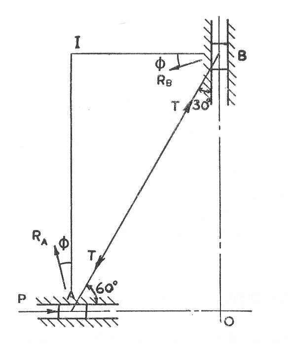
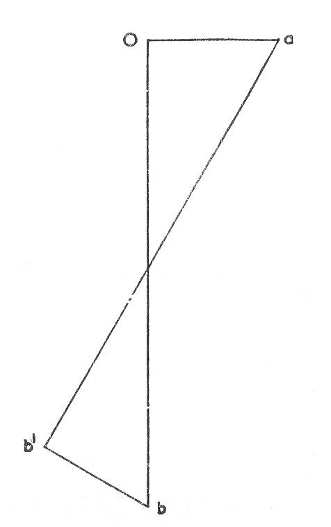
Find the horizontal force P required to drive the mechanism, at an instant when , the velocity of A being then 3 ft/sec to the right and the acceleration of A is 5 ft/sec.sq. to the right. (U.L.)
Example 10
If in a mine shaft at the equator, the mine cage is allowed to drop freely down the shaft, all frictional effects being ignored, a side thrust develops between the cage and the shaft wall. Derive an expression for this side thrust in terms of the cage weight W ad the period t during which the cage has dropped. Assume tat the earth rotates once in 24 hours.
Hence if the mine cage is replaced by a small heavy weight, dropped from ground level from the exact centre of the circular cross section of the shaft, determine the position at which the weight first touches the side or bottom of the shaft. The shaft is 20 ft. diameter and 10,000 ft. deep. Note the radius of the Earth is irrelevant. (U.L.)
Example 11
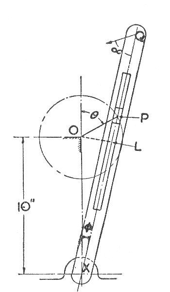
In the crank and slotted lever mechanism shown in the diagram, the crank OP is driven at a uniform speed of
radians per second. If OL is the perpendicular from O onto XQ, the centre line of the slotted lever, prove that the angular acceleration of the slotted lever is given by:-
Hence or otherwise find the acceleration of the point Q in magnitude and direction when the crank angle (U.L.)
Example 12
The diagram shows a link mechnanism which the link OA rotates uniformly in an anti-clockwise direction at 10 rads. /sec. and AC is pivoted at B. The length of the various links are OA = 3 in.; OB = 6 in.,; BC= 6 in.; CD = 12 in.
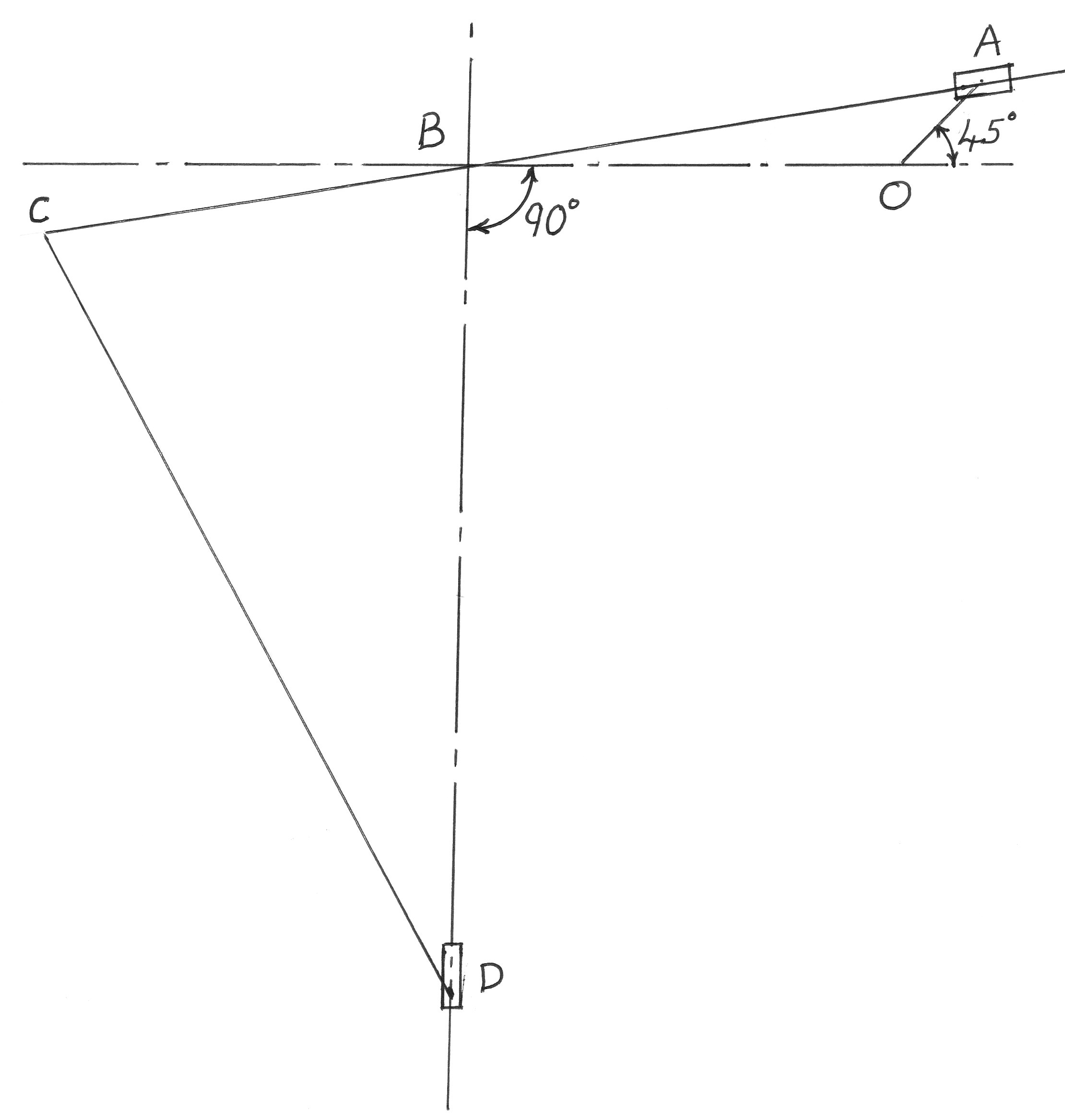
Determine, for the position shown, the instantaneous acceleration of D. (U.L.)