
Clutches
Pressure is the force per unit area applied in a direction perpendicular to the surface of an object.
The term powertrain or powerplant refers to the group of components that generate power and deliver it to the road surface, water, or air.This includes the engine, transmission, driveshafts, differentials and the final drive.
A drive shaft (which includes the clutch) is a mechanical component for transmitting torque and rotation, usually used to connect other components of a drive train that cannot be connected directly because of distance or the need to allow for relative movement between them. The drive shaft includes also clutch.
A force is any influence that causes a free body to undergo a change in speed, a change in direction, or a change in shape. Force can also be described by intuitive concepts such as a push or pull that can cause an object with mass to change its velocity , i.e., to accelerate, or which can cause a flexible object to deform.
Friction clutches with examples on singler, multiple and conical plates
You're viewing an older version of this page (#3725). View the current version.
Introduction
By definition a Clutch is a device by which two shafts or rotating members may be connected or disconnected either whilst at rest or in relative motion.
Examples of types of clutch are:
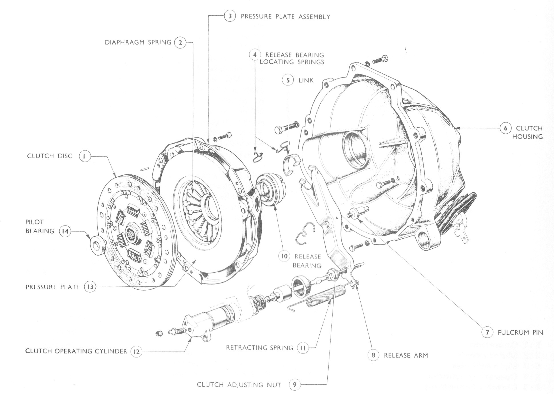
- Automotive. These are usually single pressure plates and are found on cars trucks and tractors.
- Centrifugal. Often found associated with small engines where it is required that the drive is connected once a predetermined engine speed is reached.
- Slipping Clutches are usually a safety feature and are designed to slip at some preset torque so protecting against damage.
- Dog Clutches are quite different to any of the above in that they do not rely on friction and it is generally necessary for the two shafts to be stationary when the clutch is either engaged or disengaged.
Plate and Disc Clutches
There are two types of friction clutch which operate on similar principles and which are widely used. These are:
Single Plate Clutch
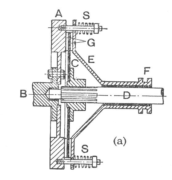
This is shown in the above diagram. The operation is as follows:
- The flywheel
is bolted to a flange on the drive shaft
.
- The plate
is fixed to a boss which is free to slide axially along the driven shaft
to which it is splined. It therefore rotates with shaft
- Two rings
of special friction material are riveted or bonded to
or alternatively to plate
- The presser plate
.
- A number of springs are arranged around the clutch ( Shown as
) so as to press the two friction surfaces together.
The Clutch operates by moving the withdrawl sleeve to the right. This compresses the Springs are removes the pressure between the friction surfaces. Hence it is possible to start of stop the driven shaft at will.
Multi Plate Clutch
The diagram shows a multiplate Clutch.
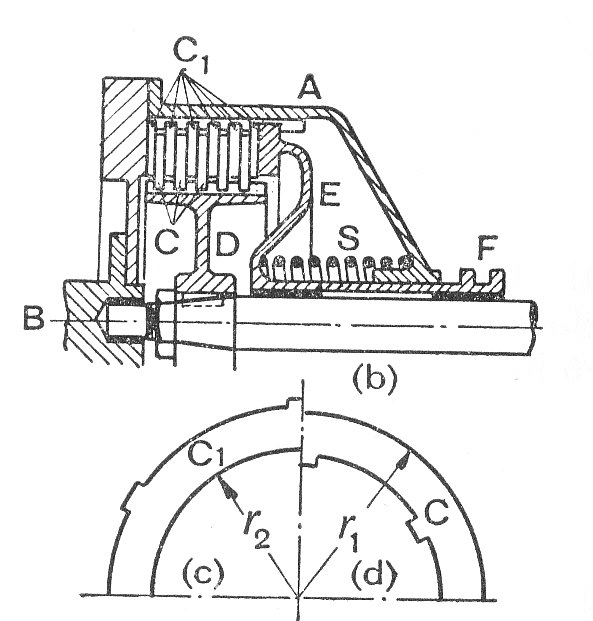
The operation is very similar to the single plate clutch but the area of frictional surfaces is greatly increased. It should be noted that as the discs are free to slide axially under the spring pressure, each pair of contact surfaces is subjected to the same full axial load.
Analysis
Diagram adapted for flat plate.
The frictional force on the circular element shown on the above diagram:
where is the intensity of normal pressure between the surfaces
By Moments about the axis, the total friction Torque is given by:
The total axial thrust is given by:
Equations (#2) and (#3) can be integrated once the variation of with radius is known. Two particular cases are considered here.
Uniform Pressure
and
Combining equations (#4) and (#5)
Uniform wear
In this case = a constant
and equation (#3) can be integrated to give:
Similarly,
Eliminating from equation (#8) by using equation (#7)
Note that assumption of uniform wear is usually preferred since it results in a lower calculated torque for a given value of .
It is normal for each plate in a clutch to have two working surfaces ( One on each side) and since they are arranged in series the axial load is transmitted equally through each plate. Consequently if the number of plates on one shaft is then the torque transmitted as calculated from equations (#6) or (#9) must be multiplied by
.
Example 1 [imperial]
A car engine rated at 12 h.p. gives a maximum torque of 65 lb.ft. The clutch is of the single plate type and both sides of the plate are effective.
If the coefficient of friction is 0.3, the mean axial pressure is limited to 12 lb./sq.in. and the external radius of the friction surface is 1.25 times the internal radius, find the dimensions of the clutch plate and the total axial pressure which must be exerted by the springs.
Let and
be the external and internal radii of the friction surfaces.
Then the total axial thrust,
Inserting values from the question,
Using equation (9) and remembering that the clutch plate is two sided.
Substituting for ,
The required Torque is 65 lb.ft. = 780 lb.in.
From which and
and
- The total axial pressure is
Example 2 [imperial]
A multi-plate friction clutch is required to transmit 100 h.p. at 3,600 r.p.m. The plates are alternatively steel and phosphor bronze and they run in oil. The coefficient of friction of 0.07, the mean axial pressure is 20 lb/sq.in.and the internal radius of the friction surface is 0.8 of the external radius, which is 5 in.
Find the number of plates required and describe their arrangement.
The area of each friction surface The total axial thrust on the plates =
The friction torque for each pair of contact surfaces is found using equation (9)
But the total torque to be transmitted,
But the total torque to be transmitted,
Where is the horse power and
is the speed in r.p.m. Hence,
Therefore the number of effective friction surfaces required,
Hence, the plates need to be arranged so that there are ten surfaces at which slippage can take place. To achieve this there will be a total of eleven plates of which six will rotate with the driving shaft and five with the driven shaft.
- The number of plates is
.
Example 3 [imperial]
A centrifugal clutch has four blocks which slide radially in a spider keyed to the driving shaft and make contact with the internal cylindrical surface of a drum keyed to the driven shaft. When the clutch is at rest each block is pulled against a stop by a spring so as to leave a radial clearance of 0.25 in. between the block and the drum. The pull exerted by the spring is then 100 lb. and the mass centre of the block is 8 in. from the axis of the clutch.
If the internal diameter of the drum is 20 in., the weight of each block 15 lb. the stiffness of each spring is 200 lb./in. and the coefficient of friction between the block and drum is 0.3 find the maximum horse power that the clutch can transmit at 500 r.p.m.
The operating radius of the mass centre =
The centrifugal force of each block:
The spring force which pulls the block towards the axis of the clutch is:
The Normal Reaction =
So the Maximum friction per block is the normal reaction times the coefficient of friction i.e.
The total torque for the four blocks is the frictional force the drum radius
The maximum horse power,
- The maximum horse power is
Example 5 [imperial]
A friction clutch is required to transmit 45 horse-power at 2,000 r.p.m. It is to be a single plate disc type with both sides of the plate effective. The pressure is applied axially by means of springs and is limited to 10 lb./sq.in.
If the outer diameter of the plate is to be 12 in., find the required inner diameter of the clutch ring and the total force exerted by the springs. Assume that the wear on the plates is uniform and that the coefficient of friction is 0.3.
From the given horse-power,
When uniform wear occurs is a constant and the maximum pressure is at the inner radius
hence,
.
Using equation (2). Note that the torque will be double because there are two operating surfaces.
Hence from equations (#1) and (#2)
or
Solving the above equation (by trial and error), i.e. the inner diameter is
Using equation (1),
- The inner diameter is
- The total force is