
Dynamics of Geared Systems
The acceleration of geared systems and the methods involved in calculating the acceleration of combined linear and angular motion
You're viewing an older version of this page (#3563). View the current version.
Introduction
When a geared system accelerates or decelerates there is a change in the total inertia of the system. Clearly the value of this increase or decrease depends upon the speed ratios of the various parts of the system.
The Acceleration of Geared Systems
- Suppose that two shafts A and B are geared together and that the speed ratio
- The total moments of inertia on the shafts are
It is required to find an expression for the torque on shaft A which will produce an angular acceleration of this shaft of
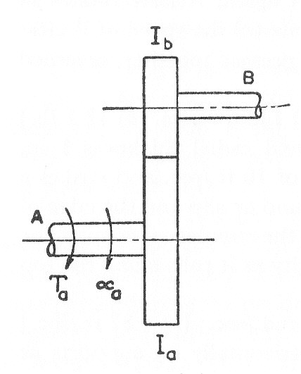
- The torque on shaft A required to accelerate
- This will produce an acceleration of shaft B of
- The torque required on shaft B to achieve the above acceleration on
- This would require a torque on shaft A of
- The Total torque on A is thus given by
is called The equivalent moment of Inertia referred to shaft A
Clearly the argument above could be extended to any number of shafts which have fixed speed ratios with the reference shaft.. It is worth noting that the same acceleration of the system shown in the above diagram could be produced by a torque applied to shaft B of:-
The Total Kinetic Energy of A and B
But since
Combined Angular and Linear Motion
There are many cases where masses moving with linear motion are connected by a fixed speed ratio to inertias in angular motion. Instead of dealing with the two motions separately, it is possible to reduce the system to one of the following:-
(a) An equivalent angular motion
For example. To find the torque required to give an angular acceleration of to the winding drum of moment of inertia I and radius R which is being used to raise a load W on a cable wrapped round the drum.
This method is used in worked examples 2; 7; and 8
(b) An equivalent linear motion
For example. The linear acceleration, on the level, of a car of weight W and engine torque whose wheels have an inertia of
and radius r and an engine with an inertia I_E and a gear ration G, is found from:-
See Example 9
Worked Examples
The following worked examples can be viewed by clicking on the red button.
Example 1
Two gear wheels A and B are mounted on parallel shafts so that they may revolve separately or may be meshed together externally.
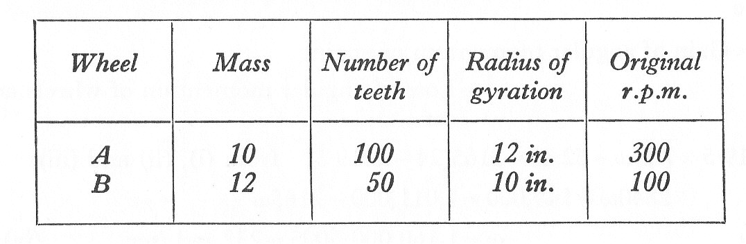
The wheels were originally turning freely in the same direction.
Find:- (a) The speed and direction of rotation of wheel A, if the gears are suddenly meshed, assuming that there is no back-lash of the teeth.
(b) The loss of energy in ft. lb. due to impact. (U.L.)
Example 2
A car weighs 1650 lb., road wheels 26.4 in. diameter. The moment of inertia ,I, of the rotating parts is and for each road wheel
. The clutch is disengaged; the engine is idling at 500 r.p.m., the car is coasting at 18 m.p.h., the bottom gear of
is engaged and the clutch pedal is suddenly released. Find the change in speed of the car and the change in kinetic energy. (U.L.)
Example 3
Whilst accelerating, the driving torque at the input shaft A of a single-stage reduction gear has a constant value and the resisting torque at the output shaft B is also constant with a value of
. The respective moments of inertia of the two shafts systems are
and
and the speed of A is n times that of B. Show that the acceleration of B is given by:-
and find the gear ratio for which this has a maximum value.
If is equivalent to 150 lb. at 7 in. radius and
is equivalent to 750 lb. at 9 in. radius and if
show that the required value of the ratio is about 5.19 and find the requirement for the output shaft to attain a speed of 240 r.p.m. if is initially at rest.
Example 4
A motor shaft A rotates G times as fast as a shaft B geared to A. If the torque on A is constant and and
are the moments of inertia of A and B respectively, find an expression for G when B has maximum angular acceleration. Evaluate the value of G when
and
.
If a steady driving torque of 45 lb.ft. is applied to A and a variable resisting torque is applied to B, find the time to increase the speed of B from 150 r.p.m. to 240 r,p,m, when the resisting torque varies directly with the speed and has a value of 75 lb.ft. at 150 r.p.m. (U.L.)
Example 5
In a gear unit the input and output shafts are parallel and directly geared to rotate in opposite directions with a speed reduction of 4. Friction losses can be neglected. If the input to the unit is 30 h.p. at 1400 r.p.m., find the externally applied fixing torque which must be exerted on the unit casing. The direction of the applied torque at the input shaft may be considered positive.
If the inertias of the input and output shafts and connected parts are equivalent to 350 lb. at 8 in. radius and 450 lb. at 12 in. radius respectively, and the resisting torque at output is constant, find the additional constant torque which must be applied at the input to raise its speed from 1400 r.p.m. to 1500 r.p.m. in 1 sec. and also the associated fixing torque on the casing.
Example 6
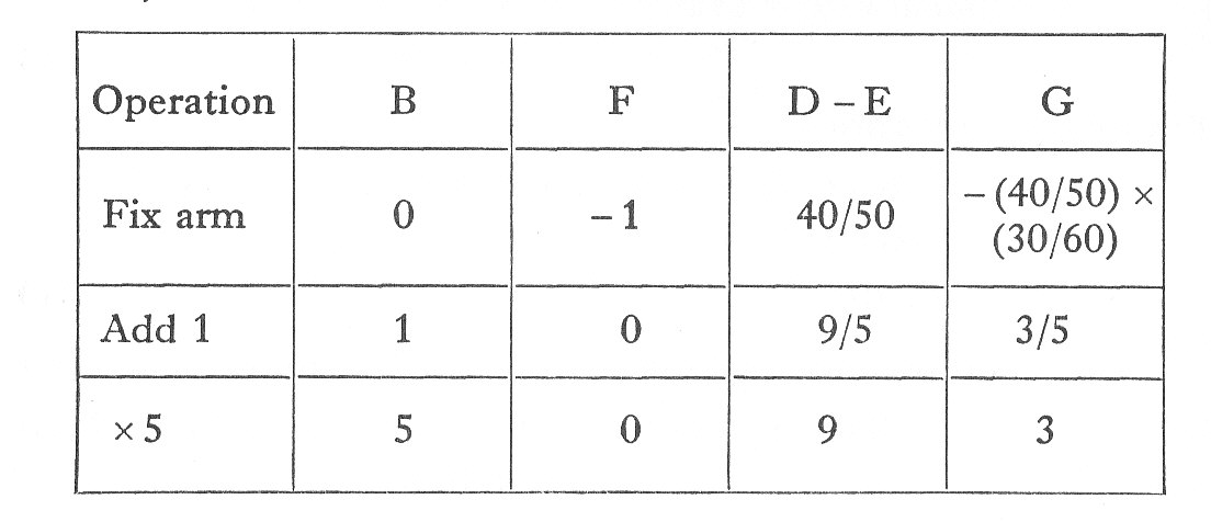
In the epicyclic train shown in the diagram all the teeth are of 4 d.p. Wheel F (40 t)which is mounted on shaft A is stationary.
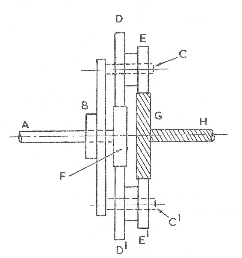
D(50 t) and E(30 t) are made of one piece of metal and can rotate freely on a pin C which is attached to plate B. A similar pair of pinions and
are mounted on a pin
. B can rotate freely on shaft A. Wheel G is mounted on the driving shaft H. The polar moment of inertia of the disc B including the two pins C and
is
D and E together weigh 7 lb with polar radius of gyration about their own centre-line 0f 3 in. G has a polar moment of inertia of
Find the torque on shaft H to accelerate the system so that B has an angular acceleration of (U.L.)
Example 7
A motor-cycle engine gives a torque of 18 lb.ft. at 2000 r.p.m. The moment of inertia of each road wheel is and that of the engine parts is
. The effective diameter of the rear wheel is 25 in. and the total weight of the machine and rider is 400 lb.
If the speed reduction between engine and rear wheel is 9 to 1 and the combined effect of rolling resistance and windage is assumed to amount to 40 lb. Find the road speed and acceleration of the motor-cycle at the above engine speed.
Example 8
The engine of a motor-car runs at 3420 r.p.m. when the road speed is 60 m.p.h. The weight of the car is 2400 lb. The inertia of the rotating parts of the engine corresponds to 24 lb. at a radius of gyration of 0.48 ft. and that of the road wheels is 240 lbs at 0.8 ft.
The efficiency of the engine and transmission is 0.9 and the wind resistance is 200 lb. The road wheel diameter is 2.5 ft.
Estimate the horse-power developed by the engine when the car travels at 60 m.p.h. with an acceleration of 3 ft./sec. (U.L.)
Example 9
A supercharged road-racing automobile has an engine capable of giving an output torque of 700 lb.ft., this torque being reasonably constant over a speed range from 60 to 160 m.p.h. in top gear. The road wheels are of 30 in. effective diameter and the back-axle ratio is 3.3 to 1. When traveling at a steady speed of 100 m.p.h. in top gear on a level road the horse-power absorbed is 75.
The vehicle weighs 2100 lb.; the four wheels each weigh 90 lb. and have a radius of gyration of 10 in.; the moment of inertia of the engine and all parts of the differential is
Assuming that the resistance in lb.wt. caused by windage and road drag varies as the square of the speed, determine the time taken for the speed to rise from 60 m.p.h. to 160 m.p.h. in top gear, at full throttle, on an up-grade of 1 in 39 (U.L.)
Example 10
Note. As 60 m.p.h.is equivalent to 88 ft./sec , 160 m.p.h. is 235 ft./sec and 100 m.p.h. is 147 ft./sec.
Let be the wind and road resistance, where v is measured in ft./sec.
Then at 100 m.p.h.:-
Treating the problem as one of linear motion, the equivalent weight of the car engine and wheels (See"Combined angular and linear motion part (b)") :-
This must equal the equivalent mass of the car times the acceleration.
Rearranging and integrating