
Transmission of Power
The transmission of Hydraulic Power through pipelines. Includes Nozzles and Jets, the conditions for maximum Power Transmission , Jet reaction and the efficiency of transmission.
You're viewing an older version of this page (#3773). View the current version.
Introduction
The transmission of power through pipes is both common and widespread in its application. Two examples are the large diameter pipes are used in many hydroelectric schemes and the comparatively small bore pipes used to connect the various pumps; motors and rams used on earth moving plant and machine tools.
Power Transmission in a Pipe
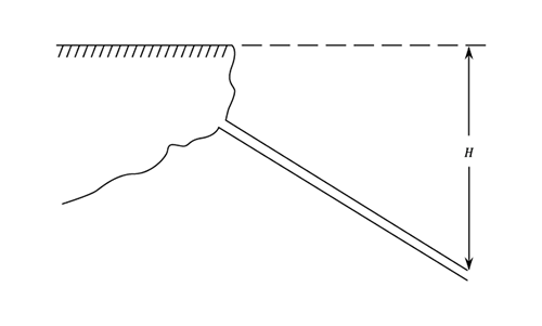
The efficiency of power transmission for the pipe is given by:-
Applying Bernoulli's equation to the pipe and ignoring pipe entry losses
Thus the efficiency of Power Transmission can be written as -
The Conditions for Maximum Power Transmission
i.e. The head lost due to friction is one third of the Total Supply Head.
To see the proof of this statement please click on the red button
The efficiency of Power transmission for Maximum Power
This is given by:-
The condition for Maximum Power transmitted is rarely used in practice since:-
- The efficiency of transmission is low and that means that water is wasted.
- The velocity in the pipeline is high and this can give rise to dangerous Water Hammer effects when valves are closed.
For these reasons it is normal to limit water velocity to a maximum of 6 ft./sec.
Nozzles
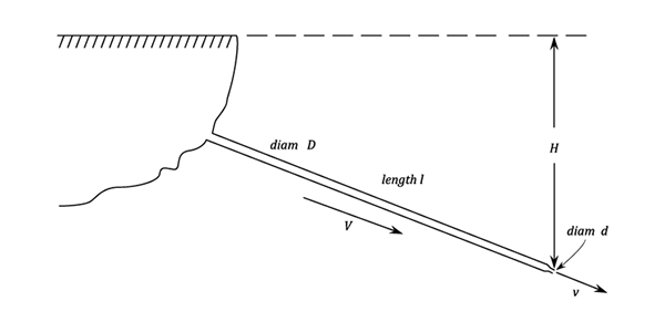
It is assumed that the Head H is the head behind the nozzle and that all
pipeline and valve losses have been accounted for elsewhere. There are, of course, losses in the
nozzle itself and the actual velocity of discharge will be less than the theoretical value by one to
five percent. This is catered for by the use of The Coefficient of Velocity. ; The
Coefficient of Contraction
; and the Coefficient of Discharge
:
- (13)
- (14)
- (15)
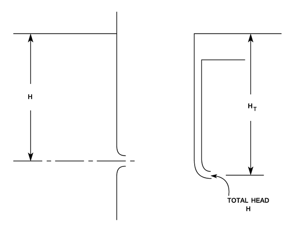
The head Lost in the Nozzle
For the proof of the above please click on the red button
Efficiency of the Nozzle
i.e.
Thus
The nozzle diameter for maximum power transmission
To see the proof of the above please click on the red button
Jet Reaction
The jet reaction is the backward force exerted on the nozzle and the pipe and is equal and opposite to the force exerted by the jet on a fixed plate.
i.e. The jet reaction = the mass of fluid passing through the jet per second X the change in velocity.
Nozzle diameter for maximum jet reaction
To see the proof of the above equation please click on the red button
The Efficiency of Power Transmission for Maximum Jet Reaction
Worked Examples
The solutions to the following worked examples have been hidden. To view them please click on the red buttons.
Example 1
A Nozzle discharges 175 galls per min. under a head of 200 ft. The diameter of the nozzle is 1 in. and the diameter of the jet is 0.9 in. Find the:
- a) The coefficient of velocity for the jet.
- b) The head lost in the nozzle.
- c) The horse power available in the jet.
Example 2
The water available for a Pelton wheel is and the total head from the reservoir level to the nozzles is 900 ft. The turbine has two runners with two jets per runner. All four jets have the same diameter. The pipeline is 10,000 ft. long. The efficiency of power transmission through the pipe line is 91 % and the efficiency of each runner is 90%. The velocity coefficient of each nozzle is 0.975 and the coefficient of friction for the pipe-line is 0.0045.
Determine
(a) the horse power developed by the turbine.
(b) The diameter of the jets.
(c)The diameter of the pipe-line.
(B.Sc. Part 2)
Example 3
During 9 months of each year there is an ample supply of water for a Power station and for 5 hours each day water is pumped to a high level storage basin situated at 300 ft. above the turbines. The basin supplies the turbines for the remaining 3 months of the year through two equal pipe-lines which are arranged in parallel and are 1,000 ft. long. The turbines develop 1500 h.p. for 10 hours per day during these 3 months with an efficiency of 0,86 as reckoned on the conditions at the turbine. Taking each month as 30 days, f = 0.005 and assuming that the friction is limited to 15 ft. find.
(a) The minimum size of the basin required
(b) The rate of discharge of the pumps.
(c)The diameter of the two pipes. (B.Sc.Part 2)
Example 4
In a Power Scheme using a Pelton Wheel, water is to be supplied from a reservoir,which will be 1200 ft. above the turbine, through a pipe-line 5400 ft. long. The Turbine is to produce 7000 b.h.p. at 500 r.p.m. Pipe friction is limited to 10 % of the gross head and the ratio of wheel diameter to jet diameter must not be less than 11:1
Calculate the number and diameter of the jets, the mean diameter of the wheel and the supply-pipe diameter. Assume for the jets to be 0.98, bucket speed o.45 jet speed and the efficiency of the turbine 87 %. f for the pipe friction is 0.0048 (B.Sc. Part 2)
Example 5
A twin jet Pelton wheel is supplied by 3 equal pipes in parallel each having a length , diameter
and friction coefficient
connected through a short common pipe to the nozzles. Ignoring losses other than pipe friction, find the nozzle diameters for maximum kinetic energy of the jet.
Calculate the Horse-power developed by the machine if for each pipe and given that the efficiency of the machine is
. The permissible loss of head due to pipe friction is 5% of the gross head and
(B.Sc. Part 2)
Example 6
The output of a multi-cylinder hydraulic motor is required to be 180 h.p. when its efficiency is 73 %. A hydraulic power station developing a pressure of 1200 supplies the motor through four 3 in. pipes, 2 miles long. Determine the pressure at the motor, the velocity of flow in the pipes and the efficiency of transmission. f=0.008 (B.Sc. Part 2)
Example 7
A hydraulic crane is operated by a ram fitted with a jigger. The crane is required to lift 6 tons at 4 ft,.sec. through 260 ft. once every 5 minutes. The ram diameter is 30 in.; water pressure 570 and the mechanical efficiency 83 %
A pump supplies water continually to the ram via an accumulator which can store water at the required ram pressure. Find
- The required minimum pump output.
- The minimum volumetric capacity of the accumulator
- The stroke of the jigger.
(B,Sc. Part 2)
Note. A JIGGER is a devise that increases the movement so that the load is raise at a speed many times that of the load.
Example 8
A main containing water at 980 is to be used to operate a direct-acting hydraulic lift. The minimum length of pipe between the main and lift is 900 ft. The lift which has a 5 in. diameter ram is to lift 8 tons at 60 ft./min. Assuming that 4 per cent of the cylinder pressure is required to overcome gland friction in either direction of motion and that
for the supply pipe is 0.009, determine the minimum diameter of the supply pipe.
What is the overall efficiency of the installation when the lift is operating under the required conditions? What pressure would be required in the main to prevent the lift just descending under gravity. (B.Sc. Part2)