
Incompressible Flow
An anlysis of Water Hammer based on the assumption that water is incompressible
You're viewing an older version of this page (#3576). View the current version.
Introduction.
Water and most fluids are comparatively incompressible and heavy. When they flow down a pipe, depending on the diameter and length, there is a weight of fluid in motion. If a valve at the end of the pipe is suddenly closed, the momentum of the fluid is changed and this will give rise to forces on the valve and within the pipe. This is called Water Hammer and can, depending upon the magnitude of the force, be very damaging. For this reason large pipe-lines can not be suddenly shut off and closure takes place over a considerable period of time. The problem also occurs on small bore pipes but here the effect is usually a knocking noise. However worse can happen and in the experience of the author water hammer forced apart a two inch compression coupling in a laboratory and a few thousand gallons of water cascaded down over an electron microscope.
The analysis of Sudden Valve Closure and Water Hammer can either be done assuming that water is completely incompressible and the pipe totally rigid or by assuming that there will be some compression of the water and some expansion of the pipe. These two solutions are considered separately.
This submission is based on The Rigid Column Theory. Compressibility is ignored and it is assumed that pressure changes caused by opening or closing a valve are felt instantaneously through out the pipe. In effect the water column is a solid column which can accelerate or decelerated as an entity.
The analysis of Water Hammer allowing for the compressibility of water is considered in a separate submission.
The Gradual Valve Closure
As the valve closes the pressure at the valve rises decelerating the water column.
Let p be the pressure rise above the initial steady flow pressure and the deceleration of the water column; p the rise in pressure; a the cross sectional area and l the length of the pipe.
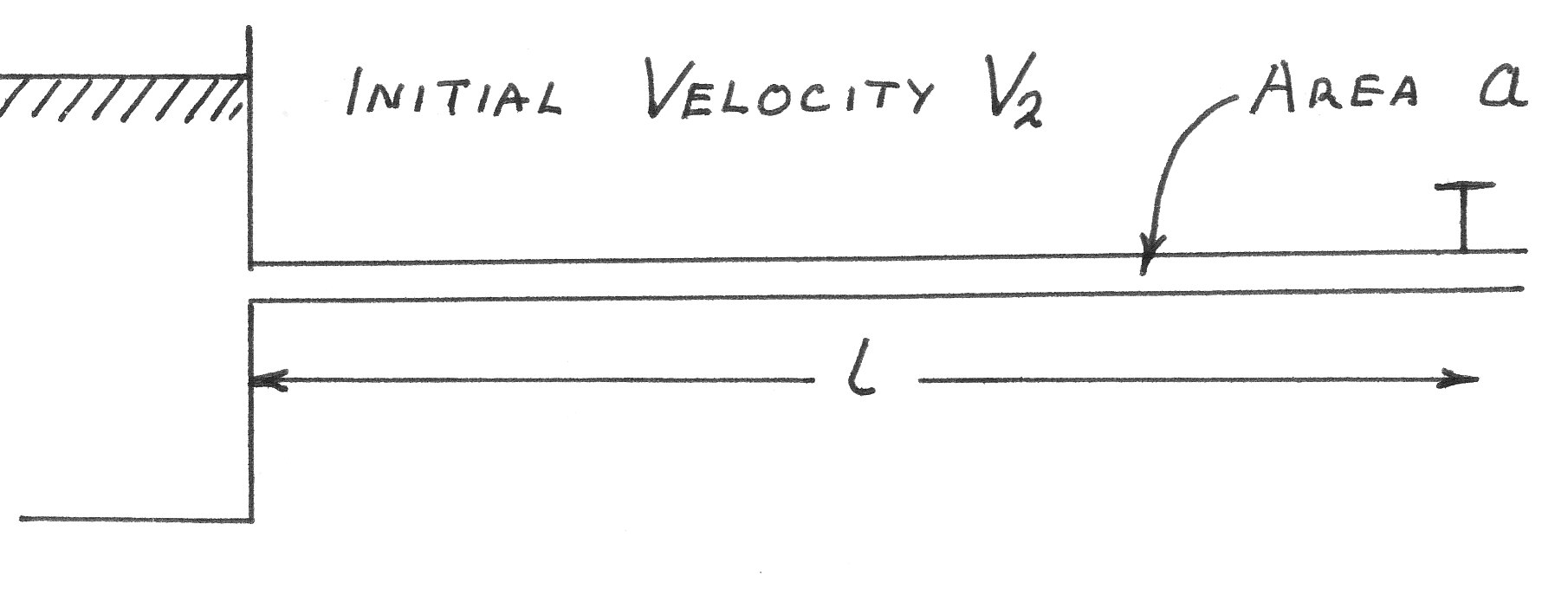
The increase in Pressure Head (H) is given by:-
to see proof click on the red button
Valve closed to produce constant acceleration
To see proof click on th red button
Valve closed to produce uniform rate of Pressure increase
Where K is a constant and T is the total time of valve closure.
To see proof click on red button
The valve closes so that the area decreases uniformly with time
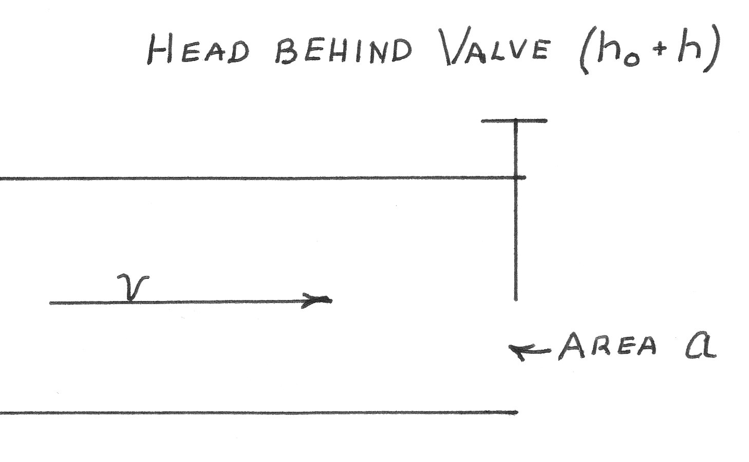
This equation again relates the maximum pressure rise directly to the time of valve closure. The difference between this and the first case is that the rate of increase in p has been controlled. The equation gives for a known pipe, the maximum pressure rise given any closure time. Note. The suffix "o" refers to to the initial conditions when the head behind the valve and is equal to the gross supply head if the friction in the pipe is neglected.
h is the Inertia head at a time t
For Valve opening
To see the derivation of this equation click on the red button
Pipe of varying Section
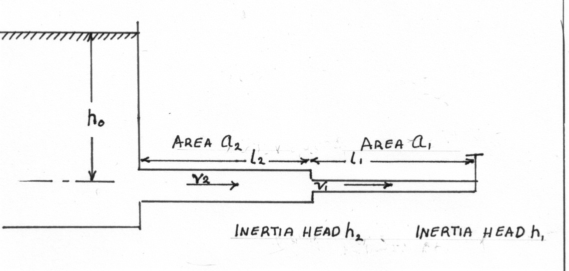
For pipe 1
Note. The above expression is the same as equation (4) with an "equivalent" pipe length of:-
And for a number of pipe sections of n different cross sectional areas:-
These equations allow the calculation of an "overall length" which can be used to calculate pressure rises under differing valve opening regimes.
To see the proofs of the above equations please click on the red button
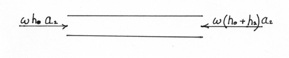

Worked Examples
N.B. The following two examples are based on the assumption that water is not compressible
Example 1
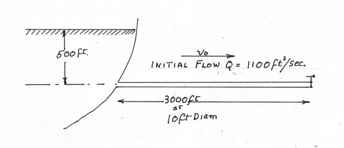
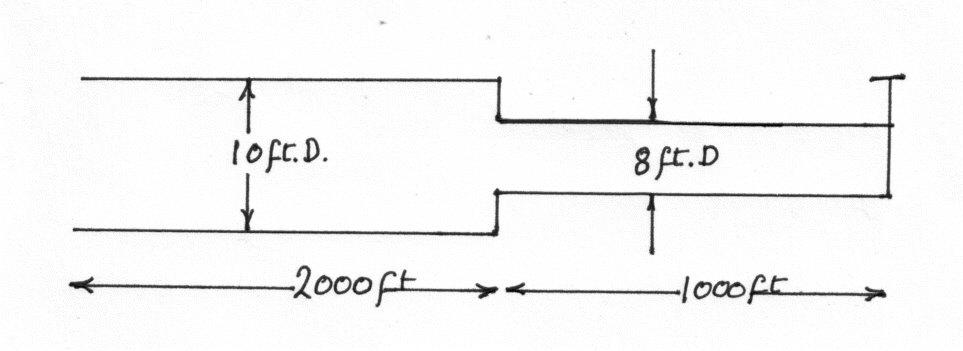
Find the maximum increase in pressure head if the valve closes in 12 seconds. @) So that the velocity decreases uniformly with time. @) So that the pressure rises uniformly with time. @) So that the valve discharge area decreases uniformly with time. @) The last 1000 ft. of pipe is 8 ft. diam. and the velocity decreases uniformly with time.
Example 2
Two reservoirs whose constant difference of level is 40 ft. are connected by a pipe 4 in. in diameter and 1000 ft. long. Flow is controlled by a valve close to the lower reservoir and the loss of head across the valve when fully open is where v is the velocity in the pipe. Assuming that the valve is suddenly opened and that water is inelastic so that there is no pressure wave, find how long it takes for the velocity of flow to attain a value equal to 0.95 of the steady terminal value. Take
for the pipe and neglect loss of head at pipe entry. (B.Sc. Part 2}