
Incompressible Flow
A valve is a device that regulates, directs or controls the flow of a fluid by opening, closing, or partially obstructing various passageways.
Acceleration is the rate of change of velocity over time.
Pressure is the force per unit area applied in a direction perpendicular to the surface of an object.
A nozzle is a device designed to control the direction or characteristics of a fluid flow as it exits an enclosed chamber or pipe via an orifice.
An anlysis of Water Hammer based on the assumption that water is incompressible
You're viewing an older version of this page (#3823). View the current version.
Using The Rigid Column Theory the compressibility of the fluid is ignored and it is assumed that pressure changes caused by opening or closing a valve are felt instantaneously through out the pipe. In effect the water column is a solid column, which can accelerate or decelerated as an entity.
The Gradual Valve Closure
As the valve closes the pressure at the valve rises decelerating the water column.
Let be the pressure rise above the initial steady flow pressure,
the deceleration of the water column,
the rise in pressure,
the cross sectional area and
the length of the pipe.

The increase in Pressure Head is given by:
\(H=\frac{p}{w}=-\frac{l}{g}\times α=-\frac{l}{g}\left ( \frac{dv}{dt} \right ) /)
By Newton's Second Law:
Pressure at Valve=Mass of water multiplied to Deceleration
i.e.
Valve closed to produce constant acceleration
Let the time taken to close the valve be seconds.
Then:
So for any given pipeline, if the maximum pressure rise is specified, the time taken to close the valve is directly proportional to the initial water velocity.
Valve closed to produce uniform rate of pressure increase
The maximum pressure rise
Where is a constant and
is the total time of valve closure.
At any instant during closure
where
is Constant.
The values of and
can be found from the known initial and final conditions
at
and
when
.
then:
And the maximum pressure rise
The valve closes so that the area decreases uniformly with time

This equation again relates the maximum pressure rise directly to the time of valve closure. The difference between this and the first case is that the rate of increase in has been controlled. The equation gives for a known pipe, the maximum pressure rise given any closure time.
Note: The suffix "o" refers to the initial conditions when the head behind the valve and is equal to the gross supply head if the friction in the pipe is neglected and
is the Inertia head at a time
.
For Valve opening
Consider the valve as a nozzle at the end of the pipe with a which is constant.
Initial flow
At a time the discharge
But:
When is a maximum:
The Maximum head
Putting:
Solving the quadratic:
This equation again relates the maximum pressure rise directly to the time of valve closure. The difference between this and the first case is that the rate of increase in has been controlled. The equation gives for a known pipe, the maximum pressure rise given any closure time.
Which must be the positive root for valve closure.
For valve opening.

For pipe 1
Note: The above expression is the same as equation (#1) with an "equivalent" pipe length of:
And for a number of pipe sections of different cross sectional areas:
These equations allow the calculation of an "overall length" which can be used to calculate pressure rises under differing valve opening regimes.
Applying Newton's Second Law for each pipe:


By continuity:
Putting equation (#8) into equation (#6)
Equation (#9) can now be inserted into equation (#7)
Note: The above expression is the same as equation (#1) with an "equivalent" pipe length of:
And for a number of pipe sections of different cross sectional areas:
These equations allow the calculation of an "overall length" which can be used to calculate pressure rises under differing valve opening regimes.
N.B. The following two examples are based on the assumption that water is not compressible.
Example 1 [imperial]
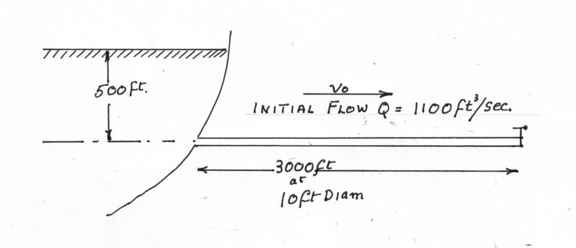
Find the maximum increase in pressure head if the valve closes in 12 seconds.
- a) So that the velocity decreases uniformly with time.
- b) So that the pressure rises uniformly with time.
- c) So that the valve discharge area decreases uniformly with time.
- d) The last 1000 ft. of pipe is 8 ft. diam. and the velocity decreases uniformly with time.
Initial velocity
- a) Velocity decreases uniformly with time.
Using equation (2) The Inertia Head
- b) Pressure rises uniformly with time.
Using equation (3)
When
which equals 14.01 ft./sec.
When = 12sec.
Thus:
And:
But from equation (4)
- c) Valve Discharge Area decreases Uniformly with time
Using equation (5) Where:
Thus from equation (4) Thus:
- d) The last 1000 ft. of pipe is 8 ft. diam. and the velocity decreases uniformly with time.
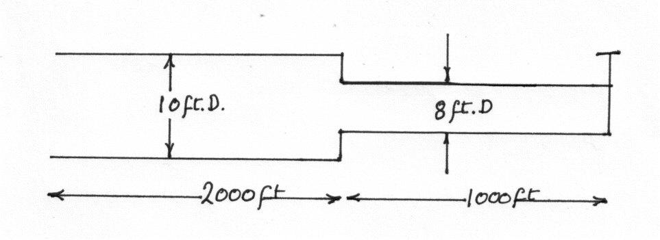
Using equation (6) The initial velocity in the 8" pipe
And from equation (7) The Equivalent Length
From equation (2) The Pressure on the Valve And the Pressure rise at the junction
Notes:
- 1. Pipe friction is small compared to the pressure rise and has been neglected
- 2. The time of closure
is greater than
- a) When Velocity decreases uniformly with time the Inertia Head
is
- b) When Pressure rises uniformly with time,
- c) When Valve Discharge Area decreases Uniformly with time,
- d) When the last
of pipe is
diam. and the velocity decreases uniformly with time,
Example 2 [imperial]
Two reservoirs whose constant difference of level is 40 ft. are connected by a pipe 4 in. in diameter and 1000 ft. long. Flow is controlled by a valve close to the lower reservoir and the loss of head across the valve when fully open is where
is the velocity in the pipe.
Assuming that the valve is suddenly opened and that water is inelastic so that there is no pressure wave, find how long it takes to attain a value equal to 0.95 of the steady terminal value. Take for the pipe and neglect loss of head at pipe entry.
Let The steady terminal velocity
Applying Bernoulli to the pipe:
Frictio head + Velocity head + The head lost in the valve i.e.
And:
When the valve is suddenly opened the water starts to accelerated and applying Bernoulli supplies the following equation:
The friction head + Velocity head + The valve loss + An inertia head
or
From equations (#1) and (#2)
Intergating:
For the velocity of flow to attain a value equal to of the steady terminal value it takes