
Axial Flow Turbines
An analysis of Axial Flow Turbines using both the |Euler and Aerofoi;l Theories
You're viewing an older version of this page (#3366). View the current version.
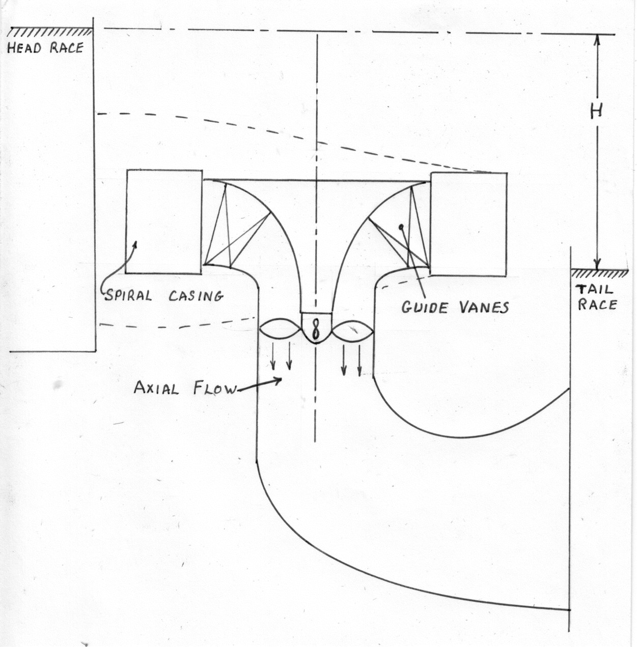
Description
AXIAL FLOW TURBINES
As with a Pump consider an element at radius r.
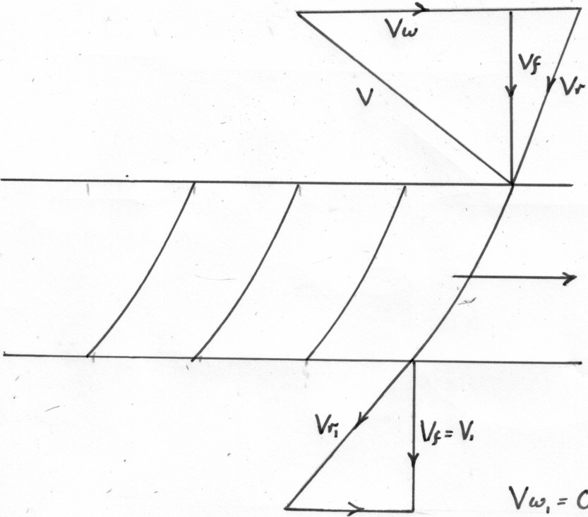
The Euler Theory
Work done by the water on the Vanes per lb. ( It is assumed that there is no whirl at exit)
Applying Bernoulli's equation across the Vanes and assuming no losses,
The Aerofoil Theory used for Turbines.
Combining the Velocity Triangles
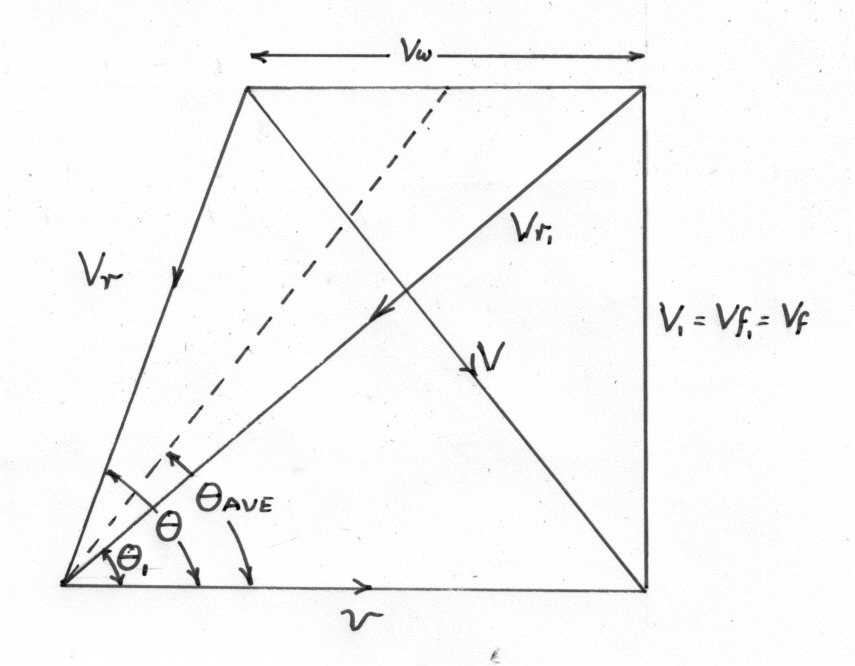
The following diagram is a sketch through one of the Vanes.
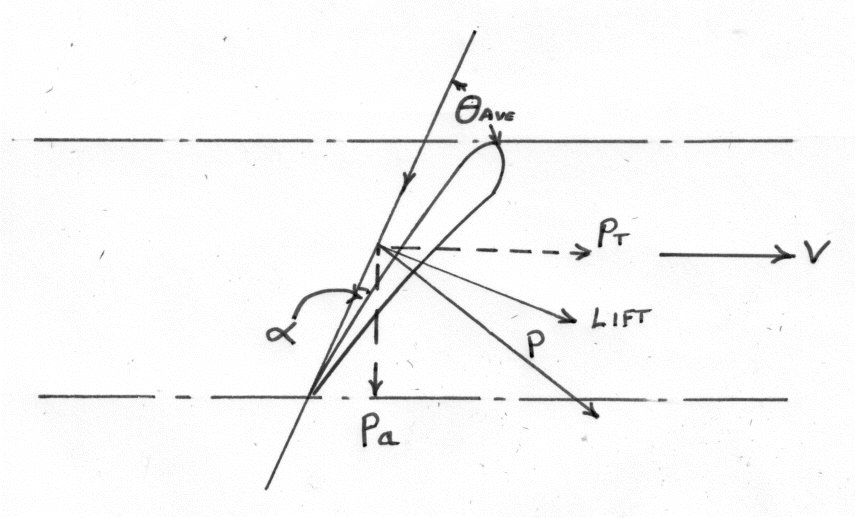
Consider the Vanes as Aerofoils in a fluid stream of Velocity in a direction
For an elemental thickness dR at a radius R
The vector sum of L and D is the resultant force P on the Vane element.
The components of P in the tangential Direction is given by:-
And the Axial component is :-
For n Vanes
The Total Tangential Force = n Pt
The Torque T = n Pt X R
The Horse Power output
Total Axial Force = n Pa = The Thrust on the Bearings