
Axial Flow Turbines
A turbine is a rotary engine that extracts energy from a fluid flow and converts it into useful work.
Leonhard Euler (15 April 1707 - 18 September 1783) was a pioneering Swiss mathematician and physicist. He made important discoveries in fields as diverse as infinitesimal calculus and graph theory.
An analysis of Axial Flow Turbines using both the Euler and Aerofoil Theories
You're viewing an older version of this page (#3711). View the current version.
Introduction
Almost all electrical power on Earth is produced with a turbine of some type. Very high efficiency steam turbines harness about 40% of the thermal energy, with the rest exhausted as waste heat.
Most jet engines rely on turbines to supply mechanical work from their working fluid and fuel as do all nuclear ships and power plants.
Axial turbine
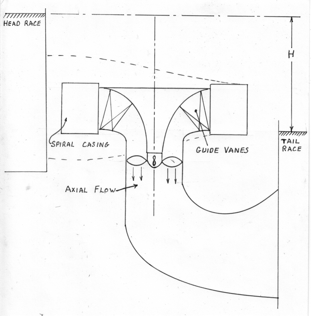
An axial turbine operates in the reverse of an axial compressor. A set of static guide vanes or nozzle vanes accelerates and adds swirl to the fluid and directs it to the next row of turbine blades mounted on a turbine rotor.
As with a Pump consider an element at radius .
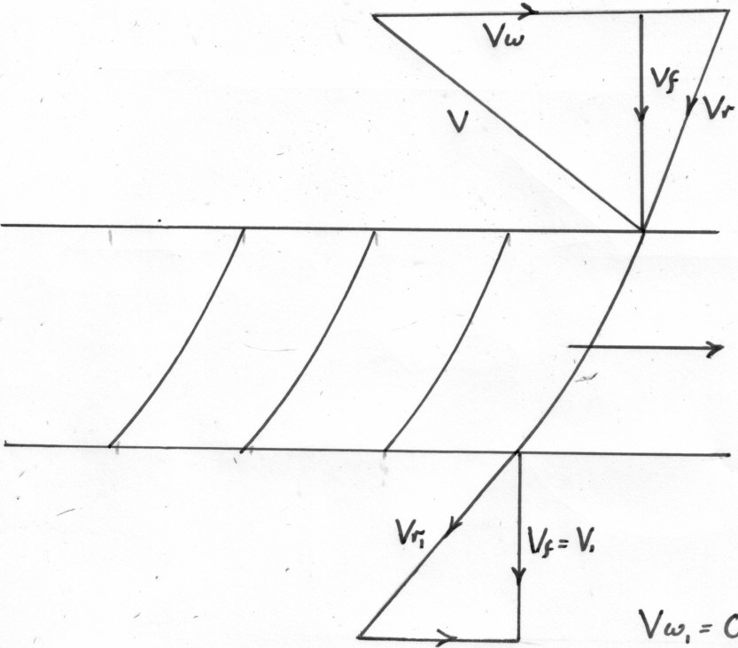
The Euler Theory
Work done by the water on the Vanes per lb. ( It is assumed that there is no whirl at exit).
Applying Bernoulli'\b{s equation} across the Vanes and assuming no losses:
But since:
Hydraulic
The Aerofoil Theory used for Turbines
Combining the Velocity Triangles:
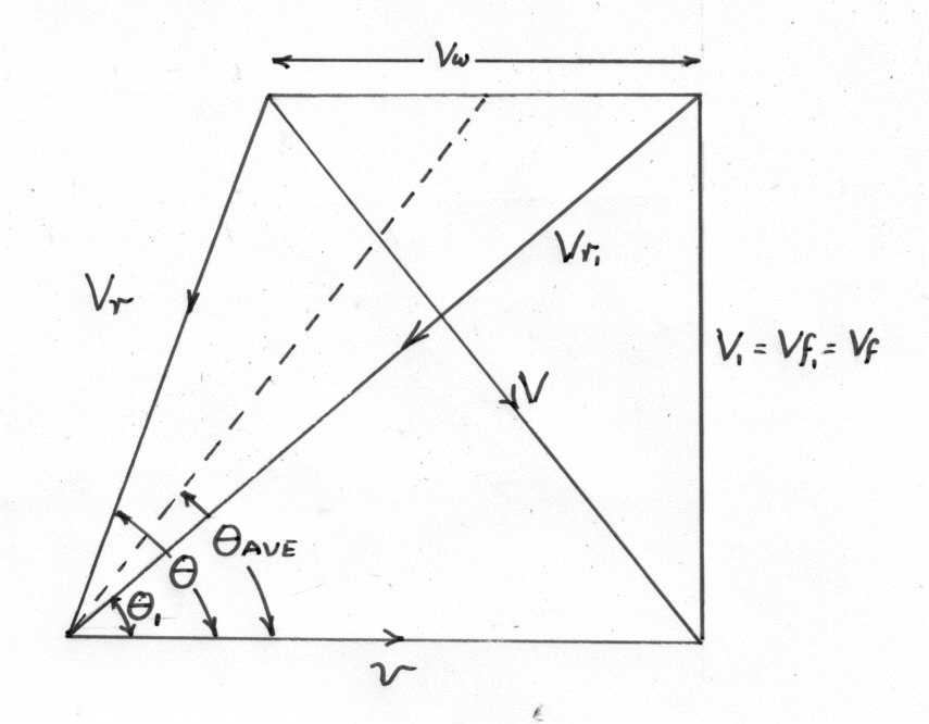
The following diagram is a sketch through one of the Vanes:
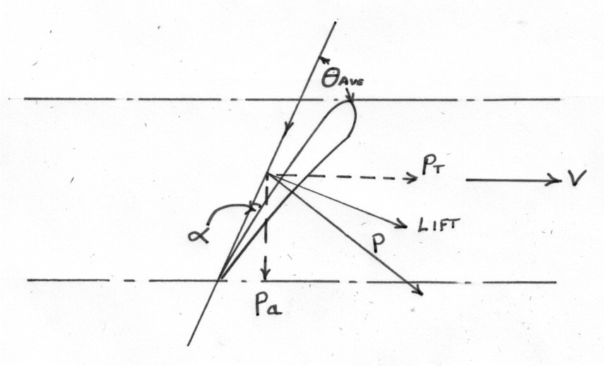
Consider the Vanes as Aerofoils in a fluid stream of Velocity in a direction
.
For an elemental thickness at a radius
.
Lift
Drag
(where Chord)
The vector sum of and
is the resultant force
on the Vane element.
The components of in the tangential Direction is given by:
And the Axial component is :
For Vanes:
The Total Tangential Force =
The Torque
The Horse Power output
Total Axial Force The Thrust on the Bearings.